Peter wrote:
Yes – exactly what I have been getting at.
And this is confirmed by the following performance table
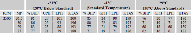
For the same MP/RPM the BHP (and FF) is lower the higher the temperature, and so is the TAS.
Airborne_Again wrote:
Does this analysis make sense?
I made a mistake assuming that changes in thrust and parasitic drag cancel because they are both proportional to air density. Since in cruise thrust is equal to total drag, thrust will actually decrease more than parasitic drag does. But this will only reinforce the effect of decreasing TAS, so the conclusion still holds.
Just look in other POHs than your TB20. There are table of MAP to achieve the same % power, and table or charts for TAS vs DA.
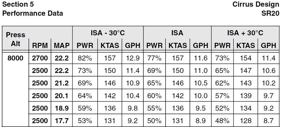
Cirrus SR20 G2:
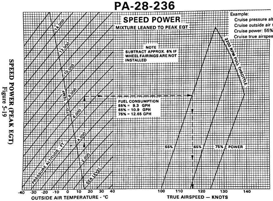
PA28-236:
That table is weird. How can you have 157 157 154? That is a strange relationship.
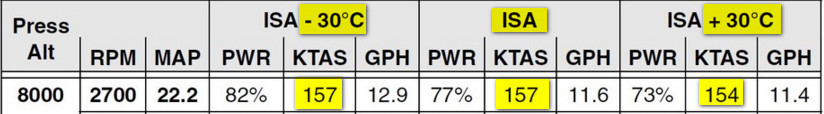
In that table the power is not constant. The trick in your question is really to balance additional drag vs additional power. It doesn’t have to be linear, especially as we near MCP.
bookworm wrote:
Power required is drag * v or proportional to rho v^3 at a given L/D (say, best glide). So if the density is 3% lower you get 1% more speed per power. And the density goes down by about 3% per 1000 ft. So it’s about 1% of speed/power or distance/energy per 1000 ft of density altitude.
So let me first correct what I said previously. For the same angle of attack (for example, best L/D) at a particular weight, which also means the same corrected/indicated airspeed, the drag is constant and therefore the thrust required is constant. The true airspeed is v (which depends on the density). The distance per unit time is v. The power required (energy per unit time) is the (constant) thrust required multiplied by v. So the distance per unit energy has a v both top and bottom: the v cancels out and the distance per unit energy doesn’t depend on v, and doesn’t depend on the density. At low density i.e. high altitude you fly faster, but you also use more power.
This is what nobbi says above, and underlies the simplicity of the Breguet range formula. Distance per unit energy depends only on the engine and prop efficiencies and the L/D ratio, not the air density and therefore not the altitude. We choose the L/D by choosing the IAS we fly at.
It’s a little counterintuitive for most of us us because, as Peter says in Post 1, GA aircraft do not usually fly at best L/D. For the same TAS on the fast side of the drag curve, at higher density altitude the IAS will be lower and therefore closer to the best L/D. So at practical GA speeds, the higher you fly the better the distance per fuel consumed.
Over the last few days I have been trying to explain the non-density effects in those C172 POH max climb tables I mentioned, and I can now reproduce the tables to within 30fpm. But I could only make it work if I had power vary with the square root of temperature, actually 1/sqrt(T), everything else held constant.
Of course, the Universal Gas Law tells us that air density varies with pressure and temperature as p/T, so for a given pressure, the air density varies with temperature as 1/T. Also, I was always taught that in a properly leaned engine, fuel burn rate and power are proportional to air density, and you could just use atmospheric density, so what was wrong?
I looked around on the internet, and after reading through lots of dross, I discovered that I had been taught wrong, that the right formula has been known for almost a century, and is:
With everything else held constant, especially ambient and manifold pressures, engine power varies roughly with the air temperature T as 1/sqrt(T), even though the air density varies as 1/T.
This is equivalent to saying that the air density varies as 1/T and so falls with temperature, but the volumetric efficiency varies as sqrt(T) and so rises with temperature.
So the bottom line is that engine power is helped by colder air being more dense, but not as much as the “obvious” 1/T formula would suggest, and so power is proportional to pressure/sqrt(T).
Briefly, the reason is:
1) Fuel burn depends on air density in the cylinder at the end of the induction stroke, not density in the atmosphere.
2) Atmospheric air is warmed by the engine (e.g. cylinder wall) on its way to filling the cylinder, and becomes less dense.
3) Cold atmospheric air starts off denser than hot air, and remains denser in the cylinder, but the key point is that cylinder walls warm cold air faster than hot, because of the greater temperature difference.
4) This reduces the relative advantage of cold air, and the empirical square root formula is the result.
Turbo-charging is more complicated, so this post is only about normally-aspirated engines.
What I found is listed below, but I should warn you that I am not an automotive engineer, still less an expert on aero-engines, so you should make your own mind up!
======
First of all, you can see the square root heuristic quite nicely in the Cirrus table above, where eg:
82% x sqrt( (272-30)/(272+30) ) = 73.4%, and
53% x sqrt( (272-30)/(272+30) ) = 47.4%
I can’t make any sense of the turbo-charged engine data table before that. However, that inlet air has been heated by compression, and perhaps cooled again after, so the simple warming formula will not apply, though a version corrected for inlet temperature could.
The rest of this text only applies to normally-aspirated engines.
You can also see the square root heuristic in plot 4 of this ancient NACA Report 45 [ local copy ]The “theoretical” degrees C temperature correction factor is given as (273+T)/273 which reflects the change in air density when temperature alone changes.
However, the “empirical” correction factor is given as (523+t)/523, which is close to the square root of (273+T)/273, (see Note 1).
NACA Report 190 [ local copy ] makes a similar claim, and further argues that the reason for the square root heuristic lies with the heating of the inducted air.
This 2013 Master’s thesis by Husaboe starting around pp11-14 [ local copy ]also refers to the square root law as the “Taylor formula” which uses pressure and the square root of temperature. His thesis is on small engines though, so may not be relevant here, but he did lead me to Taylor.
According to the comments on Amazon, Charles Fayette Taylor is a well-known figure, having worked for the Wright Brothers, and written the one-time ‘bible’ for ICE engineers:
“The Internal-Combustion Engine in Theory and Practice” Amazon link
Ordinarily I would wonder how relevant a 1985 ‘bible’ is, but given the recent citation, and the age of our engine designs, I bought both volumes. The relevant part is p186, Vol 1, (1985 edition). The square brackets show where I replaced his mathematical symbols with descriptive text.
Quote:
Figure 6-19 shows the effect of changing [inlet temperature] on volumetric efficiency for two typical spark ignition engines. The fact that [volumetric efficiency] increases with increasing [inlet temperature] indicates that the principal effect is a reduction in [inlet air temperature rise within the cylinder]. The higher [inlet temperature] goes, the smaller the mean difference in temperature between the gases and the walls and the smaller the temperature rise during induction.
The fact, shown in Fig 6-19 that [volumetric efficiency] varies very nearly as [square root of inlet temperature] has been observed in many spark ignition engines.
Since inlet density is proportional to [reciprocal of inlet temperature] the product [inlet air density times volumetric efficiency], hence the mass flow of air, varies as [reciprocal of square root of inlet temperature].
This relation is now generally accepted as a good approximation, and the output of spark ignition engines is usually corrected for air temperature changes by assuming that indicated power varies in proportion to [reciprocal of square root of inlet temperature]. See refs 6.21 and 12.10.
Quote ends.
The references are to the NACA report 45 above:
Dickinson et al
“The Effect of Compression Ratio, Temperature and Humidity on Power”
NACA TR 45, 1919.
and:
Malcolm and Pereira
“The Effect of Inlet Temperatures on Volumetric Efficiency at Various Fuel Air Ratios”,
Thesis MIT Library May 1944.
My take on the physics is in Note 2 below, I think it pretty much follows what Taylor was saying, just more explicitly.
======
Note 1:
Using the binomial approximation (1+kx) approx= (1+x)^k for small x, and where “^k” means “raised to the power of k”
sqrt( (273+t)/273 ) = sqrt( 1 + t/273 ) approx= 1 + 0.5 x t/273 = 1 + t/546 = (546+t)/546 which is close to the NACA result (523+t)/523.
======
Note 2:
Ta = ambient (or manifold) air temperature
Tc = air temperature in the cylinder, after the induction stroke
Te = ‘engine temperature’ i.e. the effective average temperature of whatever warms the air between atmosphere/manifold and the end of induction. Eg inlet valve, cylinder wall, etc.
All temperatures are absolute, i.e Kelvin or degrees Rankine.
The rise in air temperature Tc-Ta will be proportional to the temperature difference between the inlet air and the cylinder walls (Newton’s Law of Cooling) i.e. k(Te-Ta) for some dimensionless constant k, where 0<k<1.
The air will also mix with hot residual exhaust gases, but as Taylor points out, the molecular weights and specific heats of residual exhaust and inlet air will be similar, so the volume of the mixture will not change much, so this should not affect the volumetric efficiency much.
For any given pressure, inducted air density in the cylinder will be a fraction Ta/Tc of ambient density, (a fraction less than one). But from the above, we can eliminate the unknown cylinder temperature Tc:
Ta/Tc = Ta/(Ta + k(Te-Ta)) = 1/(1 + k(Te-Ta)/Ta) approx= 1/(1 + (Te-Ta)/Ta)^k
where “^k” means “raised to the power of k” and the binomial approximation (1+kx) approx= (1+x)^k for small x was used.
Further manipulation gives
1/(1 + (Te-Ta)/Ta)^k = 1/((Ta+Te-Ta)/Ta)^k = 1/(Te/Ta)^k = (Ta/Te)^k
So if Te is more or less fixed, and if k is roughly 0.5, we see the observed formula:
Ta/Tc approx= sqrt(Ta/Te), varies as sqrt(Ta)
Of course, this is still a fraction of the ambient density, and that ambient density itself varies as 1/Ta, so the actual inducted air density in the cylinder should vary as sqrt(Ta)/Ta = 1/sqrt(Ta).
Therefore, given proper leaning, with a normally aspirated engine at wide-open-throttle, at a given atmospheric pressure and RPM, we should see: air mass flow through the engine, power output, and fuel burn, all vary roughly as 1/sqrt(Ta)
Similar temperature relations should also hold for throttled-back MAPs, with power varying as pressure/sqrt(Ta).
What an absolutely brilliant post, @DavidS! Many thanks.
I have edited your post to add locally stored copies of the docs, in case they disappear, which is sure to happen.
So… have I got it right that, using the small change approximation, a 1% increase in absolute temperature (i.e. an increase of 2.7 degC) would reduce power by 0.5%?
So a change from ISA to ISA+17 would reduce power by 3.1%. That is for the same fuel burn.
Peter wrote:
So… have I got it right that, using the small change approximation, a 1% increase in absolute temperature (i.e. an increase of 2.7 degC) would reduce power by 0.5%?
Yes that would be correct, with pressure and RPM held constant.
Peter wrote:
So a change from ISA to ISA+17 would reduce power by 3.1%. That is for the same fuel burn.
Not for the same fuel burn, I’m afraid. Ultimately, all engine power must come from the chemical energy in the fuel. Ordinarily, getting enough fuel into the cylinders does not limit us, but getting enough air into the cylinders can. At altitude, in a normally-aspirated WOT climb, the ambient pressure and temperature limit the mass flow of air through the engine, which in turn limits the rate we can burn fuel at, which limits our climb rate.
Not for the same fuel burn
You would appear to be saying that the peak EGT fuel flow does vary with temperature at a given pressure altitude. That in turn causes the power variation.