Final update on this silly saga:
Replacing the D-M antenna was completely pointless. The corrosion cleans up perfectly in minutes:
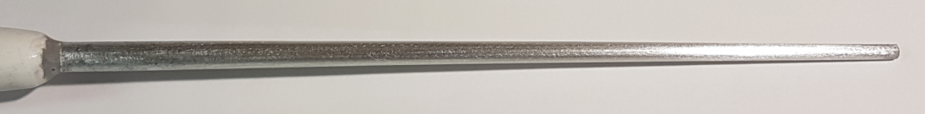
I also found I had a spare, which I bought from a TB20 owner in the US some years ago (along with an unwanted KLN94 etc). That was corroded also, and also cleaned up perfectly.
Some white paint and it’s as good as new 
Well, that D-M antenna turned out to be practically unobtainable in the UK, and I didn’t want to spend yet another pile of money importing it from the US.
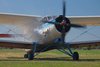
Adams Aviation said they had an “exact equivalent” which was cheaper. Amusingly that turned out to be the CI 121 mentioned above  Functionally it is equivalent so we installed that – pic here.
Thanks to all for your illuminating input.
Can anyone see a difference between the DM C70-1A and the above mentioned DM C70-3?
I am told by one installer the DM antennae are rarely used because of the higher cost, but they are shorter (which is good) due to having a matching thingy in the base.
Absolutely brilliant video. Just watched the whole thing. Thank you for posting it. It brought back stuff I did at college and univ on the equivalence of the mechanical domain and the electrical domain (mass=inductance, spring=capacitance, damper/dashpot=resistance).
We have such knowledgeable people here!
VERY GOOD film . Makes fuzzy knowledge,crystal clear.
Peter wrote:
like VSVR and whether the difference is relevant.
Here’s a really nice video from the AT&T archives that can help you understand wave behaviour (and the similarity between waves in whatever medium) and what SWR is:
SWR is a way of quantifying how mismatched your antenna is by how much power is getting reflected back. You’ll get standing waves of maximum voltage and maximum current alternately down the coax, each a quarter wavelength apart. For instance if you just shorted out the end of the coax, you’d get a voltage maximum 1/4 wave from the short circuit, and a current maximum 1/2 wave from the short (and so on down the transmission line). This can be quantified by looking at the reflected power versus the forward power (SWR meters often are ‘cross needle’ types, with a forward power needle and reflected power needle, and where the two needles cross you can read off the SWR).
The reflected energy will bounce back from the mismatched antenna back to the radio and back again until it’s either been absorbed by losses or radiated. Coax feeder performs very poorly under high SWR, and transmitters can be damaged in some circumstances (see note). (The transmitter doesn’t generally absorb the energy, the reflection from the mismatch will bounce back off the transceiver until it has all either been radiated by the antenna or absorbed by losses in the feeder). Even moderate SWR can result in poor efficiency if the coax feeder is long (and more so as frequency increases). But fortunately, feeders aren’t very long in light planes, probably rarely more than 3m.
But how much does this matter? Imagine using 3 meters of RG58 (probably the worst coax you’ll find in an aircraft), transmitting with 10 watts on 130.0 MHz:
With an SWR of 1.1, you’ll lose 0.5dB to the 3 meters of feeder on the way to the antenna, and a further 0.002dB worth of loss due to the mismatch, and you’ll radiate 8.9 watts.
With an SWR of 2.5, you’ll lose 0.5dB to the feeder as before, plus another 0.2dB to the mismatch. You’ll radiate 8.5 watts.
So an SWR of 2.5 is not really a huge deal in terms of efficiency – essentially, no one will notice a 0.2dB drop in your Tx power.
(note: the potential damage mechanism isn’t the SWR itself, but the impedance mismatch causing excessive power dissipation in the power amplifier’s transistors. Most modern radios will detect excessive SWR and will reduce power to prevent damage.)
Licensed OZ8AGB in 2004.
I was a licensed amateur too (OK1OFA, 1968-69) but I never learnt that stuff
So it sounds like the 2.5 antenna will be ok. I will try to clean up the existing one first though. One of the jobs for the Annual after xmas…
As being a Class 1 certified Radio Amateur HF operator,I can clean up some common grey areas:
-GA aircraft Com antennas are usualy of L/4 design.This design combines short length (which is desirable here) with a decent performance.
-These antennas beg for a good “ground”.Thats why we talk about clean metal surfaces and bondings.If no “ground” achieved,then you have poor performance and noise instead.
-The more vertical they are,the better.Inclined or bent types tend to intervene with aircraft body and produce higher SWR.Standing Wave Ratio idealy is 1:1 which is unachievable.That suggests that ALL emmited radiation is ejected out in space through the cables and the antenna.In the case of SWR 2,5:1 about 20% of the power is returning back to the Tranceiver ,heating it ! This Ratio is also considered tolerable in aviation.More is bad.
-One will ask why they cant manage aviation antennas with 1:1 SWR.The answer is they cant.You cant squeeze frequencies from 108 to 138 Mhz into a short fixed rod.You could if this rod could be made variable during flight (! like the old car antennas).Instead they “load” the short lenght of the rod with coil “reactance” which produces an average result.