I soldered a new in-line BNC connector to the coax supplying my Nav radio last week. The “joint” is in the tail. I think I may have messed up the “front end” of my radio.
It never occurred to me at the time but could a cheapo “Screwfix” £ 10 soldering iron do this? I suppose if there was enough mains leakage from the bit it could fry the front end transistor / FET/ GasFET or whatever is in my ancient TKM radio.
Luckily I have a spare in the shed bu what do people think, did I mess up? – Next time I’ll slide it out of the tray!
This sounds like the KX1xx radio GS input issue.
But that one has an inductor to ground so much less likely to get blown up by DC, or 50Hz AC, leakage.
Do you have a circuit diagram of yours?
A soldering iron whose bit is not earthed will have some capacitance – probably of the order of 100pF – to the heating element so the tip will have some tens (or more) volts of swing on it.
More to the point though, why would you solder a BNC connector in the first place? They are intended to be crimped. I can’t see how you could solder one and maintain the impedance matching.
There is nothing in the act of soldering versus crimping which affects impedance matching. To get a mismatch you would need to do something drastic e.g. strip off the shield or the centre conductor insulator a long way back. I once did that with USB, where I routed the four wires via a 4P2W toggle switch (to get an action cam’s USB port routed to either a USB socket or to a power supply) so for some 5cm they were not in the normal cable. The result only just worked as USB2 but was 100% solid when connected via an ancient USB1 hub which reduced the speeds by 10×. Our once resident RF expert @tomjnx had a laugh when I told him 
I always solder aviation wiring when making up stuff at home. Otherwise one needs a collection of crimp tools, and the crimp versions of the connectors are vastly more expensive. This search digs out fascinating reading material… Crimping is generally much preferred when working in the confined spaces of an aircraft.
Archer-181 wrote:
my ancient TKM radio.
TKM’s are only any use as chocks in any case nowadays so not really a problem!
Peter wrote:
Otherwise one needs a collection of crimp tools, and the crimp versions of the connectors are vastly more expensive.
Coaxial connectors seem to cost more or less the same for crimped and soldered versions.
Crimp versions of D-sub and the like may indeed be costly when using machined pins:
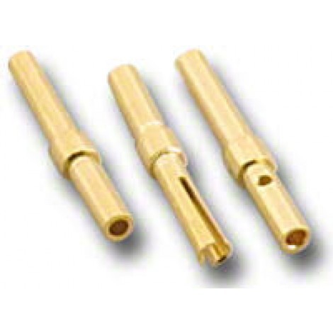
On the other hand, according to what I have read and seen, gold-plated stamped pins for crimping:
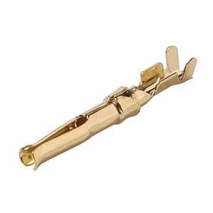
are sufficiently reliable yet inexpensive. After all, who am I to judge Garmin if they use stamped pins in their avionics?
As to the tooling, expensive military-grade AMP, Daniels and the like are excellent, but essentially you are paying for a fool-proof design; if you know what you are doing, industrial-grade tools for 1/10 the price will do the job just as nicely.
stevelup wrote:
More to the point though, why would you solder a BNC connector in the first place? They are intended to be crimped.
All the RF connectors (BNC, TNC, N, SMA) I have use a soldered centre pin and crimped shield. (You can usually tell if the centre pin is designed to be soldered – it’ll have a little hole in the side of where you poke the coax centre conductor).
All my Garmin stuff uses the machined pins though, none of the stamped stuff. I have a special crimp tool for the machined pins.
Peter wrote:
A soldering iron whose bit is not earthed will have some capacitance – probably of the order of 100pF – to the heating element so the tip will have some tens (or more) volts of swing on it.
Are you sure? At 100pF, the impedance presented to 50Hz will be on the order of 30 megohms – the radio’s centre RF pin to ground will be 50 ohms, so the voltage leaking through the mains will be utterly minuscule. Tens of millivolts swing perhaps.
Actually I think crimping is a whole lot more critical than most believe. The technology has had decades of R&D sunk into it, to make it fairly reliable. Especially with some pin types; notably the cylindrical ones (popular on the expensive Positronic connectors). About 10 years ago I sat in wigglyamp’s old shop for about 3 hrs, crimping an adaptor / bus extender for the KC225 computer, with the special DMC tool shown here
the radio’s centre RF pin to ground will be 50 ohms
Maybe, maybe not. Look at the link I posted. There is no 50 ohm terminator in a KX165A GS receiver. There is an inductor (“zero” DC resistance) which may be ~50R at the GS frequency (can you terminate a transmission line with an inductor??) but who knows what this other radio has?
There is also the scenario where the tip is charged to the top of the mains cycle, say +320V, at the very instant you touch the soldering iron on the MOSFET input.
Yeah but you’re not touching it to the MOSFET input (unless you’ve got the radio out of the tray, and in parts), you’re touching it to some wire (in this case, the coax feedline) which is some distance away, so there’s nothing that can be “instant” – you’ll necessarily have some rise time involved plus an incredibly high output impedance and the voltage will just never rise more than millivolts when it gets to the FET. And I guarantee there is some band pass filtering before you get to that FET on any radio.