it is a doppler technique
Do you know how it exactly works? It seems to me that doppler can only give you the relative velocities, but not bearing.
I cannot believe that amplitude is a relevant part of the measurement, we see how well it works using amplitude for distance estimation at the powerflarm display of Mode-S/C only targets – i.e. not usable IMO
Do you know how it exactly works? It seems to me that doppler can only give you the relative velocities, but not bearing.
Many amateur radio direction projects use this technology. Have a look at this example
You might enjoy building one of these, they are great projects and actually quite simple, especially for lower frequencies (VHF)
Yes, that’s basically the inverse setup of a doppler VOR.
But I don’t think this would work with transponder signals, the bursts seem to be too short for that. And also, targets jumping from one side to the other sounds more like a hyperbolic geometry problem to me.
A very interesting discussion. In Jan 2012 I had a TAS600 fitted displaying on a GNS530W. A few weeks ago the targets shown on the GNS were transposed, initially the thought was that I was searching the sky in the incorrect direction and that the aircraft identified was not the one displayed. This has now happened frequently and this thread is very useful in confirming the problem. Height reporting appears correct.
How does one start investigating the cause?
Testing requires specific RF test gear and/or TAS simulator or both.
Note that, according to Avidyne (Friedrichshafen 2014), a TASxxx dealer is not required to have any test equipment for it.
The large UK firm which did mine did not have any either. They parked the plane outside the hangar and watched a bizjet depart, and that was the post-installation test done.
I made it clear to the Avidyne man that I was not happy with that; I went to this firm, paying them GBP 12000, because (I assumed) they would install and test it properly. If the installer is not going to have any test equipment, then any monkey who can read the IM, do basic wiring and drill some holes could install the system and I would have saved myself a few k.
A good installation requires test equipment (though too little test equipment in my opinion).
When I got the dealership they also required to have a Traffic test set, which is in my case an IFR-6000 with traffic options.
In my opinion a network analyser with time domain measurement would also be needed (not required according the manual).
then any monkey who can read the IM, do basic wiring and drill some holes could install the system and I would have saved myself a few k.
Not true, it requires a feel for RF at least. Most installation problems are in the RF section, not in interfacing. The same is true for Stormscope systems.
OK, yes, agreed. The installer does need to be good at wiring, including RF wiring. My point was that if he is a freelancer with no test equipment, he can’t do a worse job than an authorised dealer who also doesn’t have the equipment.
Next time I do this, Jesse, I will give you a call 
Same here, Jesse. In case my service station here doesn’t solve it, I’ll call you.
In case both Peter and I show up at your shop, we’d qualify for a EuroGA volume discount, now don’t we? 
Does anybody’s TAS/TCAS system pick up targets at 12 o’clock beyond 1-2nm? (and antenna placement)
I have the Avidyne 605 installed.
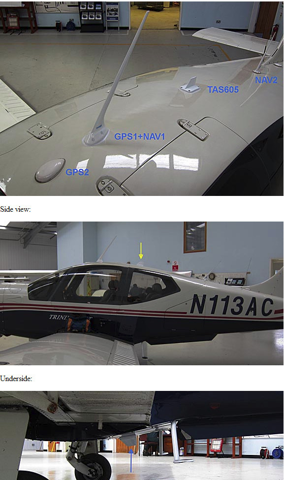
2 years on, the only issue is that head-on traffic at same or similar altitude is sometimes reported quite late. There seems to be a partial blind spot on the straight-ahead bearing, and often such traffic doesn’t appear till it is just 1 mile or so away. However, often it does appear at say 5 miles before than and then disappears! This isn’t consistent so is probably related to the quality and power of the target’s transponder installation. 1 mile is enough at GA speeds and much better than nothing. I wonder if this is due to propeller shielding?
The above pics show that the two antennae are not right on the front of the aircraft. That would have involved a lot more work, relocating the others.
As regards maximum distance, there is a strong correlation between light GA traffic and jets. Obviously, the quality of transponder installations varies a lot. The 15nm figure for the TAS605 is a software limit; the actual distance is much less and varies between 5nm and 10nm for light GA.
It could be due to the propeller shielding the signals or, on the TB20, the curve of the cockpit?