
Another test flight today. Here is an airliner contact at about 14nm and 12 o’clock
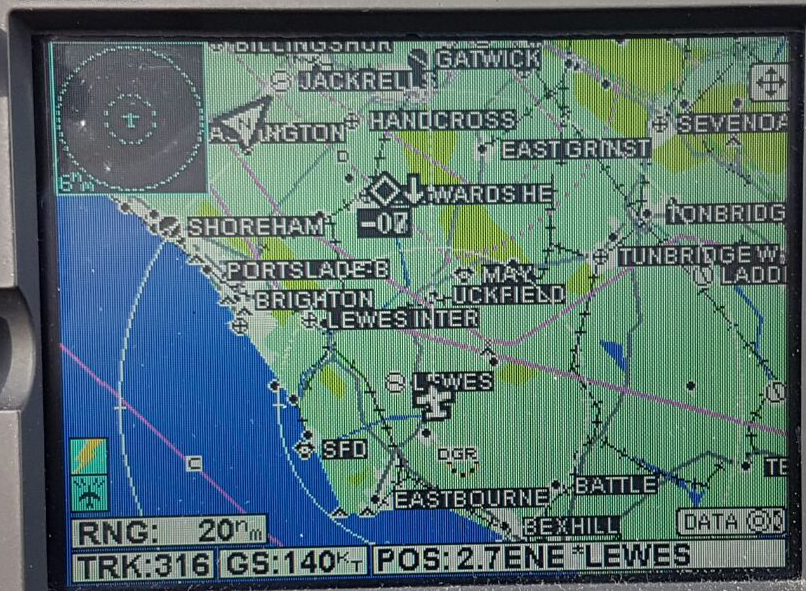
Admittedly airliners have much better transponders than GA but this is good, since the system clips the range to 15nm anyway.
I also got a C152 (yeah, one of those which didn’t have its transponder off  ) at about 8nm, also at 12 o’clock. So a massive improvement, just via a slight antenna relocation.
This post by someone who has done a lot of TAS6xx installs probably confirms that the GPS+VHF antenna would have been a problem when in front of the TAS antenna…
This is also applicable.
So often, things go round and round  As detailed in the posts llinked above, the installer who probably knew about this issue asked for an extra 2k for a DER8110 design (paperwork) package to cover the drilling of the TAS box mounting holes which was legally unnecessary (and they admitted that later, but too late) so I went to the other company…
Well, here we go…
Antennae swapped and a flight done.
The 12 o’clock improvement is dramatic – range up from 1-2nm to 5-10nm. And nothing has been lost on other bearings; I was tracking targets at 10nm all around and these were GA school planes so not anything with a supposedly good transponder installation.
I also went over the roof with a metal detector and there is metal absolutely everywhere in it. Everywhere in the tops of the doors too (I didn’t check the sides of the doors). The funny thing is that we didn’t see that metal when drilling and filing holes, so it is probably a very thin layer. It would be pretty hard to machine the composite down until the metal layer shows; if the layer is really thin you are likely to just go straight through it. And it is hard to connect to it using any other method.
Certainly any roof antennae are not short of a ground plane!
Yes you could use a standard electrician’s metal detector.
I have just been through my emails and in 2012 I exchanged about a dozen emails with Socata trying to get a drawing of it. I got a detailed drawing showing the cockpit roof side view but not the top view which might show the ground plane extent. It didn’t matter how I phrased the request; they just never got it.
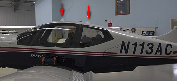
There is some metal area under the front of the two antennae:
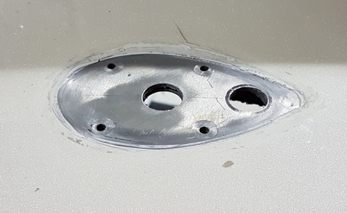
and it was easy to open up the exposed area to fit the TAS antenna.
Some time ago an avionics installer told me (or posted here?) that the gel coat layer has to be ground down until the ground plane is reached. This is probably not necessary in most cases because you can see it when you remove the old antenna. The issue which some installers would have in following that advice is that some of the antenna mounting locations (which on the composite roof are identified by having scalloped areas underneath, where the honeycomb structure (normally about 10mm thick) is thinned down to zero, leaving just the ~3mm carbon fibre top layer) don’t have a ground plane! Mounting the TAS antennae is certainly a nontrivial proposition.
The previous installer created a ground plane by gluing an area of aluminium foil on the underside and running a wire to the airframe from it. The foil would have worked but the wire would have been a bit pointless due to inductance. It was about 2m long! The guy told me at the time he measured it as x milliohms so it must be ok! We replaced it with a much shorter length of thick copper braid; the connection needs to be there otherwise static dissipation etc would have to route via the coax ground.
I hope to do a flight test this week.
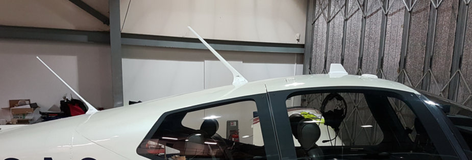
The frontmost GPS antenna is non critical. It just comes out on a BNC socket. That add-on was done by Air Touring when the plane was brand new and still on G-reg. It is for feeding a bluetooth GPS receiver – one of the old ones with an antenna input. Nothing on the market has that feature anymore.
Interesting Peter, it did not make sense to me either. Perhaps they specified that all cables were exactly the same length so there was less chance of installer error mixing up different length cables to a particular antenna.
On the ground plane, just for interest, you could connect a capacitance tester meter to detect the extent of the embedded metal – perhaps you mentioned that in a previous thread and I’m posting the same idea?
Following my last-1 post above, I have seen the latest IM for the TAS6xx (dated 2018) and my suspicion is confirmed – the four cables don’t need to be the same length
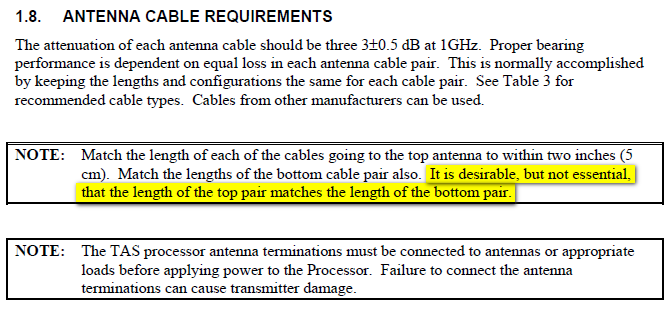
The earlier IMs don’t contain this info.
We are swapping the two antennae.
There is enough slack in the TAS antenna cables, which is crucial, and of the other antenna cables one has enough slack and I made an extension for the other – just BNC-BNC – with RG400.
Mechanically it is not trivial, thanks to some “interesting work” the TAS installer did on the composite roof.
But I did discover one thing: the ground plane which Socata says is in the roof is not actually at the current TAS antenna location. Or at least we can’t see it…
My theory is that the TAS antenna is shielded by a combination of the curvature of the roof and the fat blob at the base of the COM1/NAV1/GPS antenna.
Unfortunately, over the past few years, nobody has been able to offer a credible input on this; one based on actual experience. Kyp’s input above proves it is not the curvature of the roof alone that’s doing it.
I don’t think it is a faulty TAS box because I get the full 15nm range on all other bearings. Especially from known-good transponder installations i.e. small and large jets.
The Annual is next week and we will find out if there is enough spare cable going to that TAS antenna to enable it being moved. I think there is; there is a sizeable coil of the stuff in the rear cavity of the plane. If not, we will have to replace all four cables which will be a big job.
I’ve merged several near-identical TAS6xx threads. Near the start of this new thread there are some interesting posts regarding how the directional resolution probably works (although nobody seems to actually know).
Incidentally I don’t understand why all four antenna cables have to be the same length. Surely the two going to the top antenna must be identical and the two going to the bottom antenna must be identical. If all four had to be identical then there would necessarily be an additional requirement for the two antennae to be vertically one above the other, precisely, which there isn’t.
I wonder if you are experiencing some sort of Fresnel effect? (As opposed to just a plain reflection/ diffraction issue).
I think swapping the antennas would be a good plan!
I am still looking at swapping the two antennae as mentioned above, to move the upper TAS antenna to the front.
The only other explanation for the lack of 12 o’clock sensitivity is a fault in the TAS box. The cabling was all done in RG400; I know because I free-issued the cable to the installer.
The only concern is that this will place the combined GPS+VHF (COM1/NAV1) antenna closer to the COM2/NAV2 antenna which is further back. Is there a known issue with these antennae being spaced by about 60cm?
Does anyone familiar with this system know what the test equipment for the TAS6xx looks like and what it actually does? Almost nobody seems to have this equipment.

