
I have just built this, for powering the GNS2000 bluetooth GPS
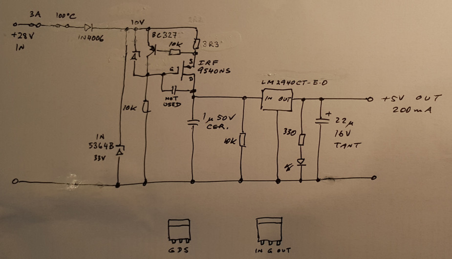
There are various single chip solutions – basically you need a 5V regulator which can take at least 36V input, and has an adjustable current limit.
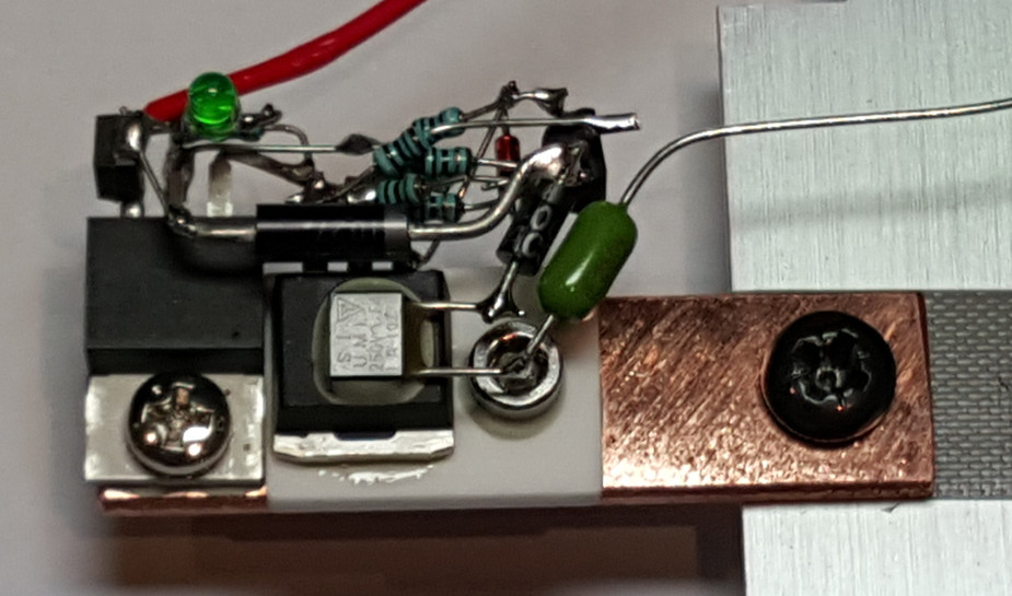
There are loads of chips which do say 1A and upwards, and the LM2940 itself is perfect, but 28V x 1A is way too much heat under short circuit conditions. When it comes to chips which can go lower on the current, there is e.g. the LT3055. But I could not find anything that is robust. The LT3055 is a tour de force in how much heat you can get out of a pin-sized piece of silicon before the tiny package explodes… typical in today’s miniature components which only need to outlast the user’s Tinder profile  So I built this massively over-engineered thing. The white block is an aluminium oxide heat conductive pad. In the good old days one could get berrylium oxide ones but not any more…
The finished thing will be potted in thermally conductive epoxy.
It will need to be bolted to some part of the airframe (hence the copper tab sticking out of it) because under short circuit conditions it needs to dissipate 5W.
You don’t seem to think very highly of PCBs, do you 
Have you tried what blows first, the fuse or the Zener that is supposed to prevent the input voltage to go over 33V?
Peter wrote:
how much heat you can get out of a pin-sized piece of silicon before the tiny package explodes
Have you ever seen a voltage regulator actually explode because of overtemperature? Most nowadays have an overtemperature shutdown built-in…
I would do a PCB in production, but not for a one-off. It’s a good point though. One can get PCBs made in China for 50 quid, and you get 5-10 then.
At 1-2A the zener would melt without the fuse blowing, but the zener is there to catch brief spikes from the starter motor etc. The fuse is a last-resort thing. As is the +100C temp fuse.
I know about the overtemp shutdown but I don’t think it works all that well. The chips don’t last long if you actually drive it into shutdown. But the other issue with those miniature chips is that you have to make a thermal connection to the pad on the bottom of the package, which is tricky. One needs to basically reflow solder it to a lump of copper, and if you do that at 360C (the normal soldering temp) it will bugger the chip.
Your 5W Zener is going to melt above 150mA… ok it can withstand 6A for 8ms, but I doubt your fuse will blow within that timeframe.
Peter wrote:
the zener is there to catch brief spikes from the starter motor
Good luck with that. If your several 100A starter motor causes spikes, there’s some logic to assume that the spikes will also be able to supply several 100A. That will pulverize your Zener die in microseconds, fortunately it doesn’t come in a glass housing and the epoxy will stop the debris from flying around your airplane.
Peter wrote:
The chips don’t last long if you actually drive it into shutdown.
Is that conjecture or do you have more information about this?
Peter wrote:
One needs to basically reflow solder it to a lump of copper, and if you do that at 360C (the normal soldering temp) it will bugger the chip.
I have found that one can easily solder these packages by hand (and unsolder and resolder…) if one has access to a good hot air blower that can be adjusted both in temperature and airflow, such as this one. Sizable amounts of solder flux makes the job easier, as does PbSn solder.
I couldn’t help thinking up an alternative:
-) two 78L05 in parallel – current limited to 2 × 100 mA inherently.
-) rudely paralleling them is no good – sum up the outputs with a couple of diodes. Either Schottky’s – the output will become 4,7 or 4,8 V – ought to be within tolerance. Or use standard 1N4004’s or so, and compensate for the voltage loss with an extra diode in series with the 78L05 ground leads.
-) on the input side, limit voltage to the 78L05’s maximum (24V?) with a crude zener diode plus a series resistor. These need to be big enough to dissipate quite some power.
-) add some capacitors at the usual places, and protection ad libitum. If adding a fuse, 3 amps seems over generous. Besides, a fuse needs to be on the other end of the supply wire. As for suppressing spikes from the starter: aren’t these avoided by keeping the avionics master OFF while starting? But if one wants to be on the safe side, there are specialised components available (TVS diodes are one kind, I think?)
Less complicated, less component count, less expensive, less voluminous.
Tom – Fair point about the zener junction not taking much heat… I am instead putting in a Fairchild 1V5KE39CA which does 1kW for 1ms.
Also I am changing the fuse for a 1A one.
Is that conjecture or do you have more information about this?
I have blown up enough of them.
Jan – the shunt regulator preceeding would dissipate too much power. Also I don’t like dissipating significant heat in plastic packages.
Certainly the supply has a CB on the start of the wire.
We use a lot of Tranzorb type varistors, much more robust than zeners, although the knee voltage is less well defined
Unfortunately, it turns out that the GNS2000 GPS has a mode (called a “flat battery” ) where it draws 0.45A…
Clearly they designed the battery charger to draw the maximum which can be drawn from USB2 (USB3 is 0.9A, as a guaranteed available level)…
So I will need to improve the heatsinking on this thingy considerably. And the whole thing could have been done with a LM78M05 which current limits at slightly above 0.5A! It will still need the input protection, however.

