FWIW, we just installed dual G5s in our club 182 and are having some serious issues with the installation. There are some minor snags, but the big one is that the GMU 11 (the magnetometer) doesn’t seem to send consistently accurate data to the G5. Heading can be off by as much as 20deg. The main problem is, that the error is not consistent. We are currently investigating the cause. It could be anything from a duff GMU11 to some firmware / software mismatch to an installation error. I’ll report back as soon as I know.
Where is the GMU installed?
zuutroy wrote:
Where is the GMU installed?
In the tailcone.
I believe my GMU 11 is in the wing tip. It is rock solid reliable
If you have a pitch trim motor back there and it’s anywhere near it, there can be some interference. Did you verify that it passee the interference test.
No pitch trim motor back there, pitch trim is manual on that bird.
Any magnetic loop can swing a compass (which the fluxgate is) quite a lot.
If the fluxgate is in the wingtip then you need to make sure any loads within the wing, say the pitot heater, and especially anything on the end of it (nav lights etc), are wired with two wires, running close together. Do not use the airframe as the ground return.
If the fluxgate is in the tail section then the same applies. What loads are there? Tail lamp?
The airframe should not be used for the return wire at all, if any significant current is involved during flight (so the starter motor is ok, and indeed the return conductor for that is usually the airframe).
I know the return for the alternator is usually the airframe, which is bad, but it tends to be ok because the fluxgate is nowhere near the alternator circuit. The alternator current does swing the compass above the panel though, quite nicely, as you change the revs and various loads…

@Archer-181 Sorry for the late response, I was away from the aircraft and couldn’t check the G5. You have to manually enable the expanded HSI, see the attached picture. 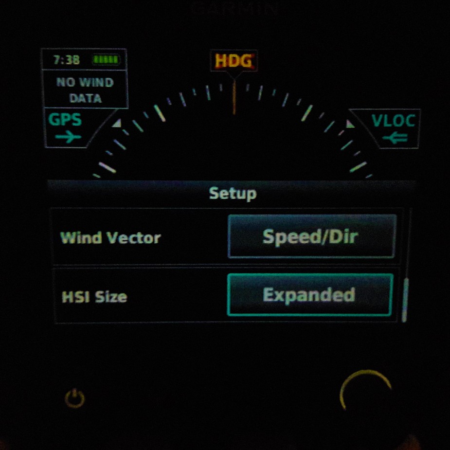
This G5 is running software version 6.40, and the probe is installed in the cabin air inlet.
And regarding the heading error: Sounds like an interference problem. Did you follow the interference test procedure according the installation manual? It wants you to move every possible control surface and use any other system according to a schedule, which, after completion, will tell you at wich time the greatest interference occurred. That should give you a pretty good hint at the culprit. Could easily be some control cables moving too close by.
CharlieRomeo,
How did you get the expanded HSI option?
Was that a later update . I’m running 6.0
I thought it was only for non-certified versions…
Thanks
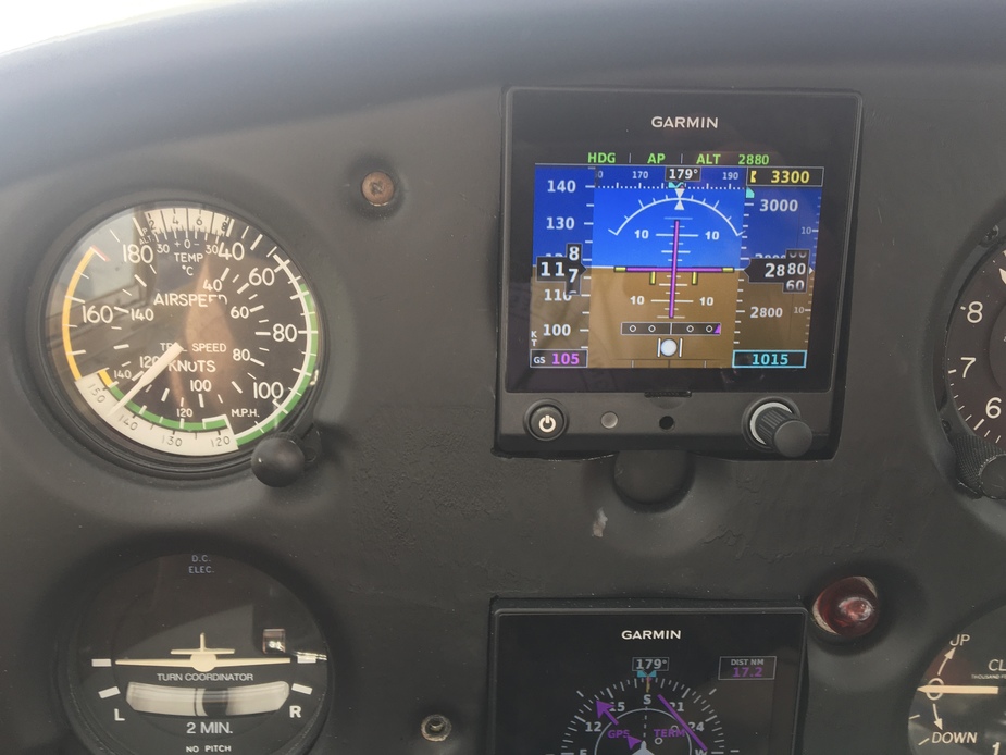
A question: does anyone know how the „ball“ in the G5 (or any other PFD, for that matter) is calibrated? And how precise that normally is?
As you can see, the ball on the PFD is slightly out to the left, the ball on the goood old TC is slightly out to the right.
In other words: which one to believe more?