Cordwood is a bit like that but not quite. This is one example
I don’t understand it because even when I was a kid, say mid 1960s, a PCB was the “right way” to build anything electronic. Well, assuming that the design was stable and didn’t have to be re-wired…
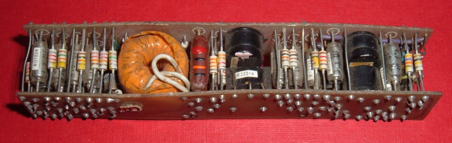
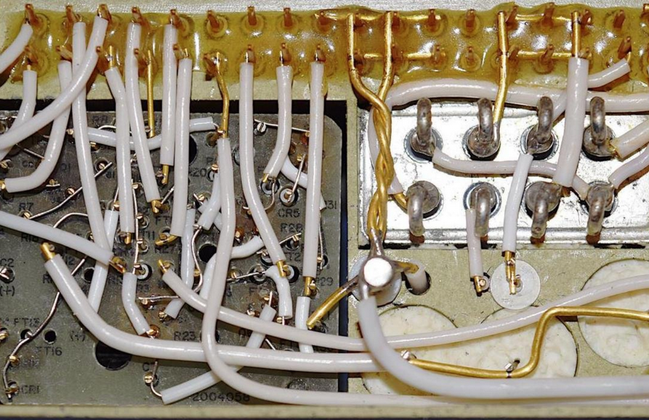
The above actually uses PCBs, anyway. The following is from the Apollo era. No PCBs, and the interconnecting wires were welded, not soldered
A lot of the parts in this autopilot are made by Sfernice which was a French manufacturer of electronic components. Clearly the designer brief was to use French parts as far as possible. Most of these old French companies have since either vanished or been taken over by foreign companies; in this case by Vishay. In fact the history of tracing OEM equivalents of Socata parts runs along similar lines; you find companies which have vanished, or been taken over by foreign ones (and the new owner often shuts down the old aviation lines).
What is quite funny is that we think nothing of a 1972 plane, and anybody who can pick up a spanner can fix it, but the electronics is incredibly ancient – and virtually nobody can fix any of it, not least because there are probably no wiring diagrams… and almost nobody in this field understands “electronics”.
I did actually get a ring binder with some diagrams with the above. Impressive hand-drawn stuff.
Do you think a French electronics designer in the 70s spoke English  ? Even today, most can barely read components datasheets.
Working with other French is so much easier. Same culture, easy phone calls, easier purchasing stuff, no customs involved, end-user agreement etc…. And we like giving business to our own.
As for the hand made stuff, I guess the small production didn’t motivate the managers to invest in tools. We are more keen to designing something on a notepad than establishing a proper, consistent production and efficient customer support. It is a bias of our ´grandes ecoles’ (engineering colleges). That killed us among other things.
As you say, French manufacturing has been wiped out since. Only the Airbus ‘ecosystem’ still lives well (because they can sell 100€ a bearing), and a few others.
Even today, most can barely read components datasheets.
That’s a very interesting point. Didn’t think of that
I am surprised that the various (mostly American) companies, who must have had distributors in France (and thus avoided the need for Customs on import) didn’t offer local support.
The Brits were very good at improvisation too. The 1960s/70s military hardware was basically handmade – just like this Baden stuff. And a lot of it didn’t work when needed… the proportion of INOP missiles during the 1982 Falklands business was said to be 30%. Concorde avionics may have been similar.
Peter wrote:
I don’t understand it because even when I was a kid, say mid 1960s, a PCB was the “right way” to build anything electronic
Cordwood construction was used (IIRC) for compactness. With the large components of the day, laying them out on a single layer PCB in two dimensions would result in a lot more surface area usage than going three dimensional with cordwood construction, and it essentially gave you a two layer PCB when such a thing didn’t exist (because you had a PCB top and bottom) making routing easier. The example you show would have to be at least five times bigger if laid out on a flat PCB (and would still be just as tall, due to the large inductor).
In those days too wire wrap was often better for high speed digital circuits because the nature of point to point wire wrap means you tend not to suffer so many issues with stray capacitance and cross talk between signals.
It’s easy to forget how fiddly routing a complex single layer PCB is (especially when you had to design it by drawing by hand!) when even the home electronics hobbyist can order one-off four or six layer PCBs cheaply today which makes routing a breeze (and a company making thousands of a thing, can have 4+ layer PCBs made for very little money per unit) and there are good open source schematic and PCB design tools.
Oh yes the days of 1-layer PCBs, especially the paxolin ones ones which would crack easily
BTW, it was possible, even in the 1960s, to do 2-layer PCBs. Before PTH, you would insert rivets in the vias and solder them both sides.
Good point about large components. But there are few in this autopilot. It looks like someone was consciously trying to avoid PCBs – or just building a 1950s design in ~1970.
Were they building so few? The Robin factory must have been historically quite busy to have built the French aeroclub fleet. With components being generally really cheap, one would always get 100 PCBs made, and that strips out much of the labour content, and then you can finally assemble the whole product in smaller batches, as the orders come in. Even if it will take 10 years to get through the 100, it is worth doing.
To hand-build one at a time is going to be incredibly expensive, as well as creating all kinds of other issues e.g. requiring absolutely superb documentation, so that – given that, over time, you can reasonably expect everybody who knows the product to have left/retired/died/etc – a complete monkey can pick up the docs and hand-build and test just one.
Were these autopilots used on aircraft other than the Robin? The technology looks like it has origins way back.
I had one of those Baden autopilots in my Robin: the system was driven of the intstrument vacuum pump, with a tube which ran to the underside of the rear seats, there was an on/off valve within reach of the pilot. The control mechanism under the rear seat was operated by a bellows connected to the aileron control wire (much like the electric motor type). Unfortunately, the bellows and rubber connecting tube were made of perishable material. I only recall it working once and decided to delete the whole system as parts and expertise were not available.
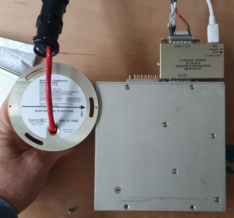
I got my hands on a faulty Sandel SG102 Mod 1 AHRS which would prob99 have been declared BER (beyond economic repair). Given that the minimum repair charge would be some $1k+ but you can buy a freshly overhauled Mod 2 unit from e.g. South East Aerospace in Florida for $1.5k, this unit was basically worthless.
So I took it apart and spent some time working out how it operates. It is an excellent product which I have in my TB20, replacing the heavy KG102 directional gyro; more details here and here.
The big connector is the Positronic (Apollo 11 era) one which is plug compatible with the KG102 and this is how (in the US) the SG102 can be installed in place of a KG102 as a like for like functional replacement, with just a logbook entry (Minor Alteration)
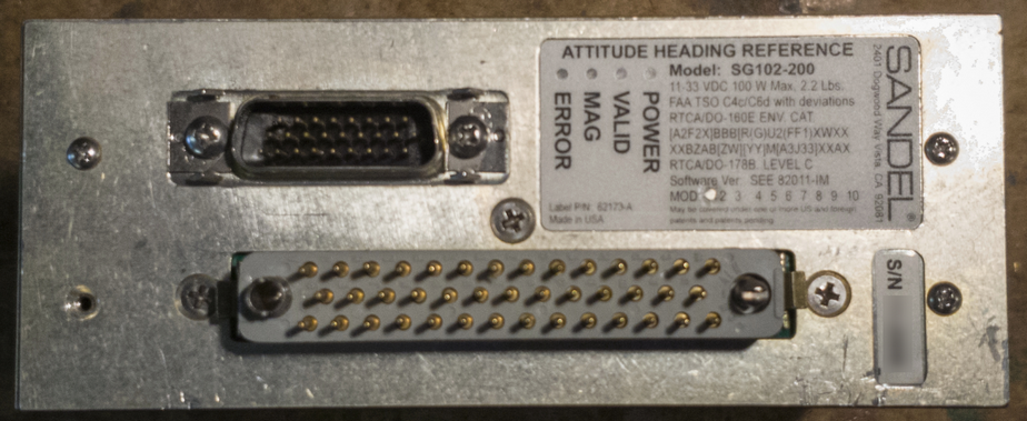
The D connector is for interfacing to the SN3500 EHSI and the MT102 fluxgate which replaces the KMT112 King fluxgate.
The metal box is part extruded and part CNC machined aluminium; very sturdy
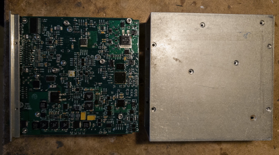
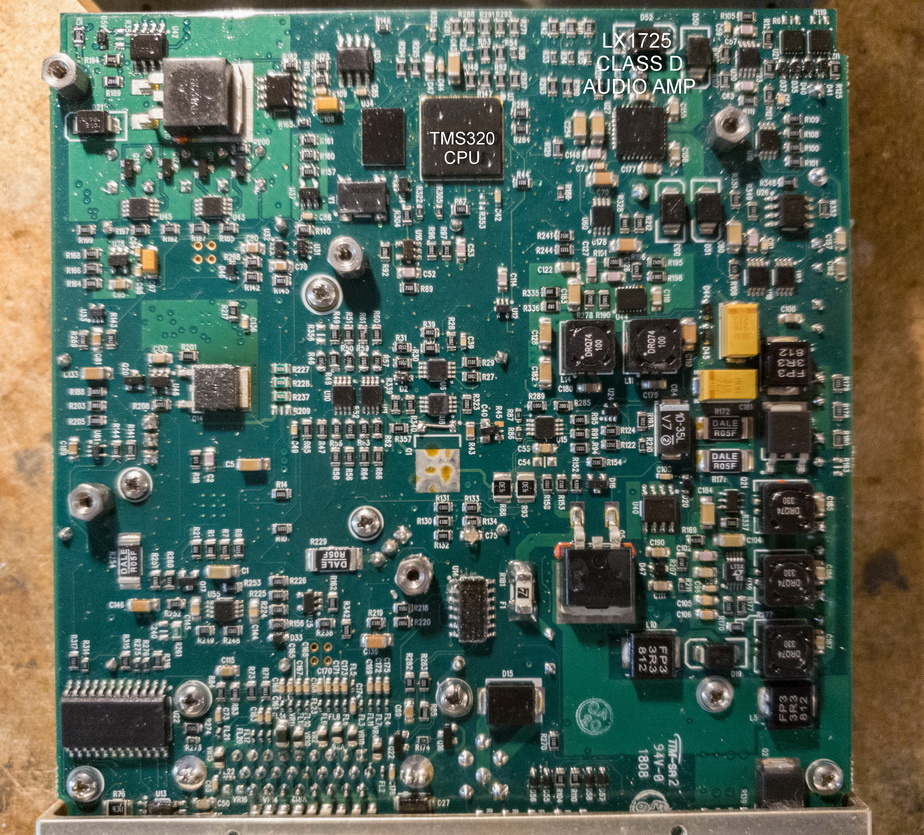
There is just one CPU – a Texas TMS320. The design was probably done in the early 2000s and it was a reasonable thing to use back then. Today the CPU business has converged and you would probably use an ARM (32F4xx or similar) but as always a designer who is an expert with one device will always outclass a designer who is a lesser expert with another one. There is also software re-use which potentially saves a huge amount of R&D…
The SG102 also produces a fairly high power 400Hz 26V AC RMS output for various avionics purposes (as a part of the X/Y/400Hz compass system; nowadays ARINC429 is often used for this but there are various compatibility issues with that). There are lots of ways of doing this using PWM principles; Sandel do it with a cunning method based around a LX1725SK 15/30 watt Class D audio amp chip which saves a lot of PCB space (but doesn’t seem to exist anymore except on chinese Ebay sites)
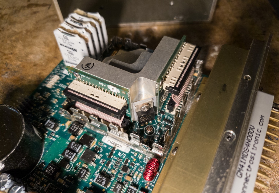
All solid state rate gyros and accelerometers drift like hell and need to be temperature stabilised to get any reasonable performance. The SG102 contains them in an insulated module so one isn’t heating the entire product to the stabilised temperature. Aspen had the same issue but didn’t do this as well and they end up heating up the entire EFD box which is prob99 why their reliability isn’t all that great…
There is a 2 farad capacitor made up of five 10F parts which appear to be in series; I think the purpose is to simply store energy for some seconds because the SG102 can have its power interrupted for that long and it comes back exactly where it was (the MT102 fluxgate too). Incidentally this is handy during engine start because you can have the avionics master OFF during starting and then the SG102 (if it was already stabilised) comes straight back online

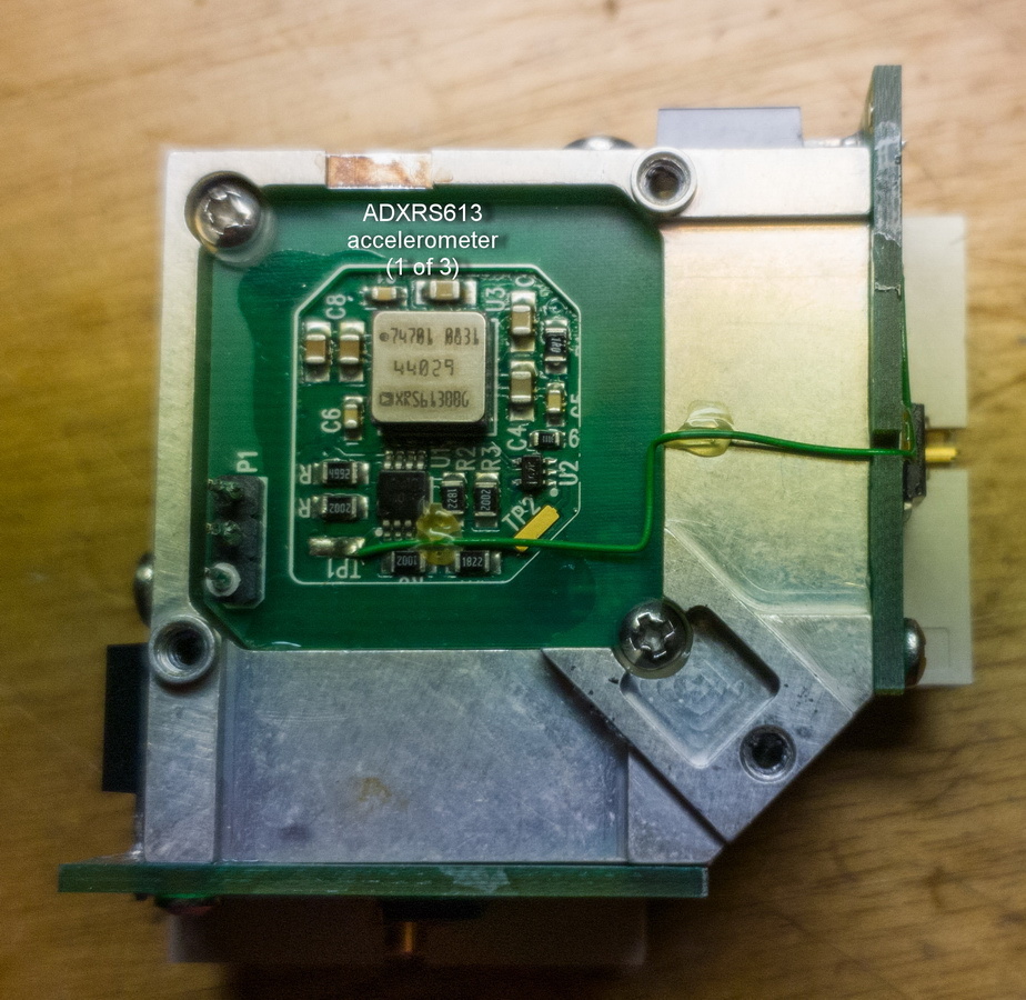
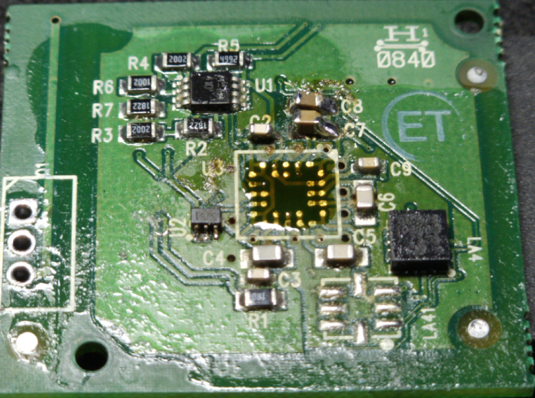
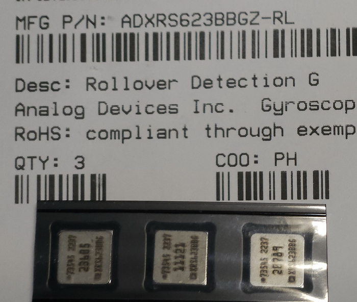
This is the AHRS module exposed. The three Analog Devices rate gyros are on the three perpendicular axes and the whole aluminium block is heated to +65C with three TO220 MOSFETs.

This is one of the three rate gyros – ADXRS613 (incorrectly labelled in the photo as “accelerometers”)
The back of the PCB in more detail. The top left is a switching PSU for the various supply rails. The bottom left is the Class D audio amp for 400Hz generation
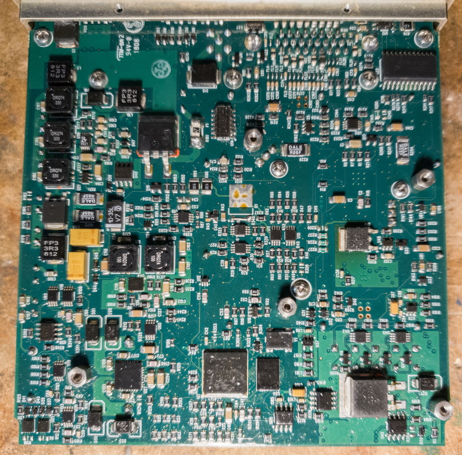
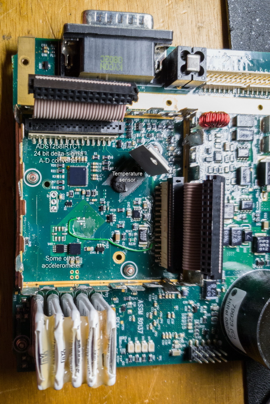
I think this A-D converter is used for converting the rate gyro and accelerometer outputs. The temperature sensor is under that blob of silicone
The back panel with the big connector on a PCB

You can monitor a serial output (RS232, or via the Sandel USB adapter, with Teraterm etc) and it is pretty obvious what most of it means. The +65C temperature is also obvious
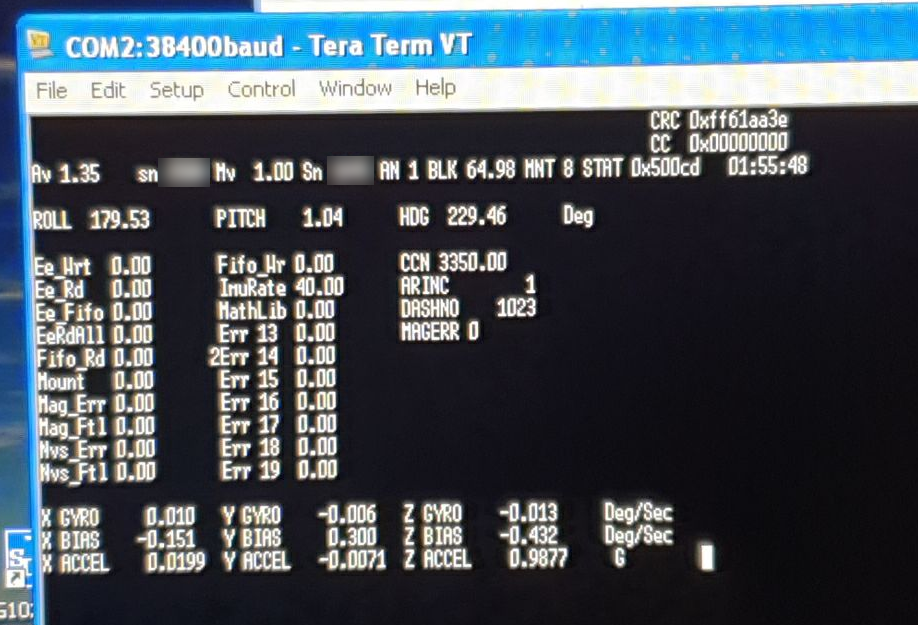
I wondered why the roll value is showing 180 (179.53). Eventually I realised the unit was upside down It also never initialises if powered-up upside down; you just get a permanent VALID error status.
I set out to try to repair it. Without the MM, circuit diagrams or any other data this would be obviously impossible unless one struck gold and found some obvious mechanical problem, a capacitor which blew up, or perhaps one of the supply rails was duff. Initially the whole thing ran as far as the data output went so the CPU and in fact nearly all of the stuff was obviously OK, and all the supply rails measured ok, but most of the accelerometer related values shown above were zero. With a product which suffers a lot of thermal cycling one always looks for bad solder joints and such like, and after some poking about I found that applying pressure to a very specific spot on the PCB made it work!

and sure as hell on the other side of the PCB, underneath the machined aluminium block, was a chip which would be extremely hard to replace
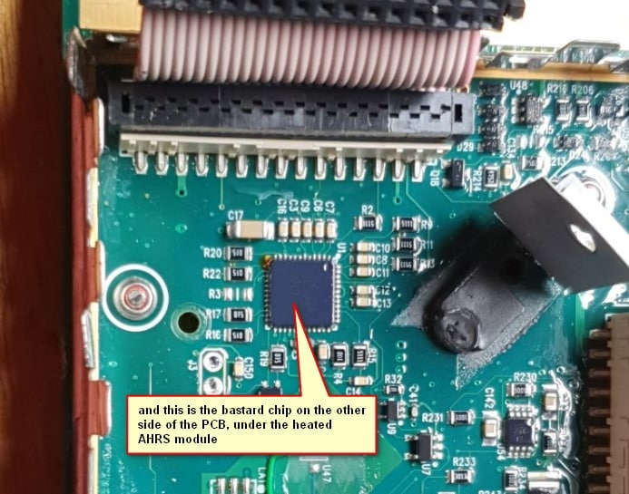
The whole PCB is painted with a conformal coating which makes rework almost impossible, as well as obscuring most component markings. With a 40x microscope like this

I found it is a ADS1258IRTCT which still exists at about £20. Lifting it off with a special hot air gun, cleaning up the mess, checking for no damage on the tracks and pads, applying solder paste, placing the new part, more cleaning, and fusing the paste with a hot air gun, and cleaning up the almost inevitable shorts due to blobs, took about 3 hours. To my amazement that fixed it! Statistically there is highly unlikely to be more than one fault on a product (which was taken out of service upon the initial fault). I had earlier tried just reheating the chip to re-flow the solder, in case of a bad joint, but it didn’t do anything, so it must have been an utterly microscopic crack in the chip, which flexing the PCB (by no more than some microns) just happened to close up the crack.
Freezing it overnight to -25C and powering it up shows no problems, so it looks like a good fix.
It was good luck the fault was not in one of the two big ribbon cables going to the AHRS module; these are notorious for going intermittent. I had this in a Tektronix scope which I managed to repair, salvaging a £2k instrument.
It is interesting they are using that accelerometer chip also: ADXL321J. I think that in the serial data output above the bottom block comes from that chip, including the +0.9877G value displayed. When originally testing the SG102 (links above) I found that it sensed the gravity vector without any apparent drift, and I don’t know how it manages to do that. However, the data sheet tells you that it does exactly that, and can be used to measure tilt!!
So the three ADXRS613 rate gyros on the aluminium block do yaw rate around each of the three axes (each one does yaw rate around only one axis) and the ADXL321J does linear G (actual G, not a “G rate” i.e. acceleration) along each of the three axes, and somehow all this is combined mathematically to generate pitch and roll and heading, to emulate the KG102 and also emit the stuff on ARINC429 for the SN3500’s reversionary attitude mode. Incidentally, Sandel have come as close as one can get to emulating a KI256 but – I spoke to their then owner – chose to not pursue that path. They could have sold an awful lot of them!
The TMS320 is probably a good CPU for 32 bit integer maths but nowadays a 150MHz ARM with hardware floats would be just as good.
Looking at the specs of a number of components, the whole box seems to have been designed for -40C minimum. That’s “automotive spec” which is nowadays easy (but wasn’t easy 15 years ago) rather than -55C to +125C “full mil spec” which is much harder and results in abominations like the King autopilot servos which use the sh1tty Globe servo motors simply because they are specced down to -55C.
Given that the AHRS module gets heated to +65C every time you fly, and the delta T over ambient of the whole box is around 25C (steady state draw is 0.3A at 28V so that has to end up somewhere) it isn’t surprising there are failures, and I am on my 3rd SG102 now in 7 years. I am sure the other AHRS products on the GA market have the same failure rate; people just don’t talk about it openly because they all need dealer involvement to fix it and nobody is going to sh1t on their own doorstep (the Aspen EFD reliability issues have been well aired though and are prob99 due to this same mechanism; all electronics hates thermal cycling). Whereas the SG102 can be swapped in minutes and since the compass calibration is stored in the MT102 fluxgate, you don’t lose that (actually you can shift it a bit by upgrading the SG102 firmware – it can shift by a few degrees – but that’s another story). Later versions of the SG102 firmware reduce the heat-up rate to make the heating elements last longer (and draw much less current at startup as a result; 2A against 5-10A) and the Mod 2 box has a much faster startup (1 min against 3 mins, handy, since during this time the aircraft cannot be moved).
I have just bought a Mod 2 SG102 as a shelf spare. I have never seen the internals of a Mod 2 SG102; I can tell you the PCB is upside down relative to the Mod 1 (and thus so are the two connectors, when the unit is mounted) and the firmware is different. It also no longer uses the elastic antivibration mounts.
The overall build quality is good. My only comment is that it would have been great to reduce the AHRS module temperature to something cooler than the +65C, but one can see how this was arrived at, given the amount of heat generated in the product anyway (the 400Hz generator is responsible for a fair bit), and one has to go for a figure which is higher than the highest possible ambient. Also the figure has to be above the max ambient required by TSO. They could have however done it so that literally only the 3 or 4 relevant devices were heated and not a big chunk of the main PCB as well. I would have split the box into two, with the AHRS stuff in one half.
Looking at a Mod 2 unit, its delta T is about 1/2 of the Mod 1 so they must have the AHRS module much better insulated, and/or it is much smaller.
The Mod 1 units can be no longer repaired if one of the rate gyros is gone because they are no longer officially available (they exist on Ebay, unused).
The repaired unit can be used as a handy source of variable ARINC429 data for testing ARINC429 products
UPDATE: the ADXRS613 can be replaced with a ADXRS623 which is a current chip, same spec, the unit works perfectly, no calibration or any setup required.
old:

new:
The BGA soldering is a real bastard. You have to clean up the board, coat with soldering flux, place the package, heat it, and hope for the best. It is actually easier to replace the unleaded solder balls on the underside of the chip with loaded (60/40) solder balls which melt much more easily, by running a soldering iron over it. The resulting balls are much smaller but that is fine.
Unfortunately, while replacing the big gyro chips can be done without any need for a recalibration of the unit, there remains a calibration procedure for the accelerometers and how to get into that is a mystery.
The Mod 1 unit shown above can have a firmware update up to v1.35, which I did. That process is also really tricky because the USB adaptor presents two COM ports and one has to muck about to get it working.
EDIT: it is possible some SG102s use an ADXL335.
Thanks for that writeup – it was very interesting. I feel your pain, I’ve just been soldering an LQFP with 0.4mm pitch (by hand)…
With a clean PCB, and good access, a lot of liquid flux applied, and a sharp edge on the soldering iron bit, one can hand solder all this stuff too. I just think that, overall, using hot air is much quicker and with luck you don’t get any more shorts than if one hand soldered it, and there is no risk of PCB damage. Also the paste I had was 1 year old which doesn’t help.
This is the whole thing running, with the fluxgate and the USB adaptor. The $1000 adaptor (which I bought from a pilot in the US a few years ago together with an unused SG102) is needed only for firmware updates; the serial comms is supported via RS232 directly to the SG102 and for the compass calibration procedure that is all you need.
A fair number of people are throwing out this stuff (installing Garmin glass etc) so there is a reasonable supply of parts on the used market.
I much prefer these non-integrated solutions because of the dramatically improved downtime situation. Just swap the box, get the A&P signoff, and you are good to fly again.
That’s always bothered me about these integrated panels – any failure and you’re AOG potentially away from home, running up expensive hangarage fees, and then needing even more expensive repairs. That and they are baked into the TC of some newer aircraft. Most of the ‘modular’ panels (going back to the six pack of steam gauges), at least most of the time you can still get out VFR and get the problem fixed at your home field.