I have this B&C backup alternator and ideally should bring in cooling air via a hose into the area shown
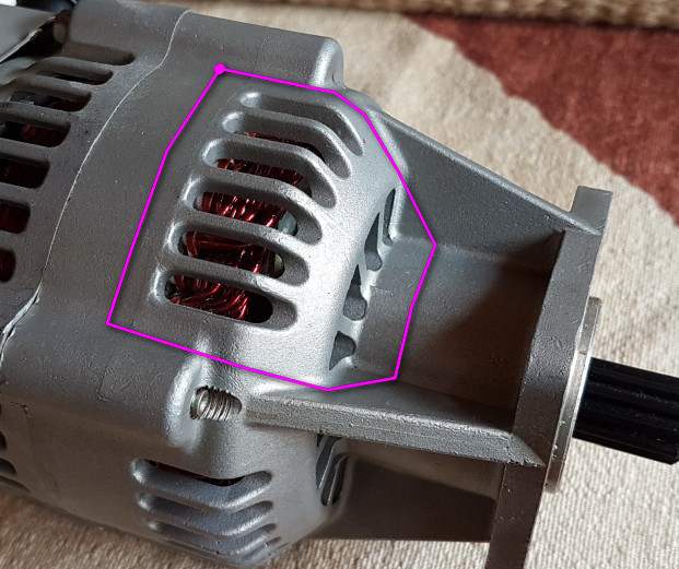
There is no obvious means of attaching something there, but I am sure that if a close fitting shape is created, structural epoxy would work perfectly well. It is fail-safe anyway; there is nothing really lost if it falls off, and the whole area is visible on a preflight check.
Forced air cooling should be worth maybe an extra 2-3A on this alternator.
Obviously the adapter can be fabricated by cutting out a complicated shape from sheet metal and welding it up but that looks pretty hard, especially if you want to do it well.
Is this possible to perhaps 3D print?
How would one make a pattern from the shape of the alternator casing? I know there is a laser scanning process but have never been involved with it.
This pic shows the desired hose attachment point for which this “adapter” is required
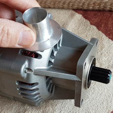
The alternator in these pics is a spare one, so that is available as a pattern.
Peter,
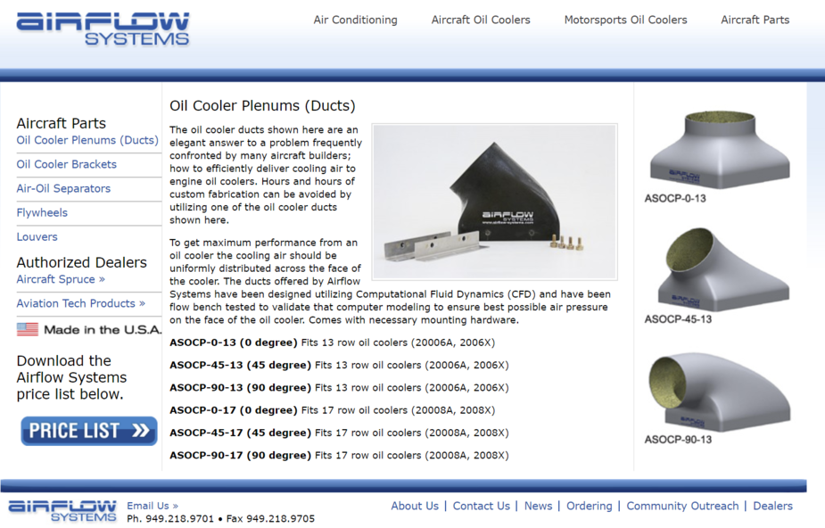
How hot does the alternator get? If it doesn’t get too hot, I would be tempted to make a fibreglass adaptor. Please see the photo of other oil cooler ducts below, I also included a main air intake plenum inlet which seems to have been done in carbon fibre, but has an aluminium flange at the inlet):
1) Cover the flange area on the alternator with tape (e.g. duct tape) to protect it from the resin.
2) Glue on a foam block (e.g. pink or blue polystyrene insulation foam – make sure you use epoxy. Polyurethane resins will dissolve the foam)
3) Shape the foam to your desired duct form with a knife and sandpaper. You could make the round connector part in foam, or you could incorporate the aluminium flange you already have.
5) You can cover the foam mold with plastic wrap and then fiberglss over it. Build up enough layers until it is sufficiently strong, say 3 to 4 mm overall. Or you can fiberglass right onto the foam and then dig out the foam afterwards.
6) Clean up the end result et voila.
Alternatively, you can get out the cardboard to make templates and make some sort of aluminium box with the correct profile and then weld your flange to the back.

Hmmm yes that foam-shaping procedure should work.
The alternator casing should not get hot… I would guess maybe +60C. I have established the upper crankcase reaches about +90C but that’s where the cylinders are. The benefit of getting some cooling air in there is to cool the copper. The standard (full size) alternator which most planes have has a cooling hose going into it for exactly this reason. You get, at a wild guess, 20-30% more output, in some extreme conditions. But those alternators have a cooling hose inlet on the plastic moulding in the back, ready to use. Also they draw air in at the back and exhaust it in the front, whereas the B&C one has a simple impeller at the back which centrifugally expels air at the back so presumably relies on it entering at the front – where I plan to bring it in.
My whole plane draws about 20A, of which 5A is the pitot heat. I am hoping to get 15A+ out of this alternator at peak engine revs, maybe more. So every bit will help.
I would have liked to 3D print a metal shape. There has been a massive amount of “technology evangelism” about 3D printing and I think it’s time to put it to a test  But one still has to construct a 3D model for that.
A large duct which covers the whole alternator (like those in your post) would be another approach but (a) they need a big inlet hose which will rob air from the space above the engine and (b) I don’t have room around the alternator.
If you’re not too cost sensitive then just get a one-off part CNC machined by ProtoLabs:
Create an account, upload your 3D CAD model, select the material, wait for the automated quote to come back, press “Buy”, part turns up in the post a couple of days later. I have been using them for years for bespoke (automotive/motorsport) parts.
If you want a hand creating the 3D model or going through the ordering process on ProtoLabs, let me know.
Hi Peter,
I provided the pictures as examples. I was envisioning a very small duct, scaled down to only cover the area you marked in pink, I just couldn’t find a quick picture of a small fibreglass duct on the internet.
Having quite a bit of experience, I could probably do this in fiberglass in an hour or two spread over a couple days.
I also worked at a contract manufacturing shop with all of the toys… 3d printer, laser cutter, CAD, CAM etc and I think you would spend ages futzing around with the models as opposed to a foam block, which you can shape in 15 minutes, mount the aluminium flange you have and then fiberglass it all. Job done before you have drawn anything in CAD.
Best of luck.
There are plenty of opensource CAD programs around now 3D printing has taken off. I’ve been having a go with FreeCAD of late and it works nicely (if not a bit retro and buggy).
My suggestion would be to tinker with making a CAD file, find a friendly forumite to print it in plastic to check the fit, then send it off to somewhere to be done in metal. At 60degC you might even get away with it being made in ABS, depending on how reliable you wanted it. As suggested above – it does take a while to get a design done though. Amazingly tricky mech design work. Never admit that to a mech engineer though…
At the risk of being helpful I can print in PLA/ABS if you wanted a small (200mmx200mmx200mm) piece for test fitting etc.
At the risk of being really helpful if you can’t work CAD I could have a pop at a design if you sent photos with dimensions of the alternator, hose connector and installation. I’m sure there are forumites who are proper engineers however that could do it right.
J
Thank you all for the suggestions.
The drawback with doing it in “plastic” is that there is no adhesive which satisfactorily bonds it, or bonds it to metal. Especially the soft plastics like ABS on which no adhesive really works properly – short of a solvent but that won’t work to metal. So I would have to strap the object to the alternator, perhaps with a long stainless steel tie. And that is tricky due to its tapered shape. Hence I was looking at metal, which I know can be glued with certain high temperature structural epoxies.
My first job is to “copy” the shape of that part of the alternator, however. I have done masses of “tech drawing” and injection moulded component design in my life but producing a dimensioned drawing in this case is not trivial. It’s a very complex shape.
I would do like Canuck but I think 3mm thick is too much. 0.8-1mm should be enough.
I would make sure to post-cure the part to 80C to make sure it doesn’t get floppy if the alternator get warm.
Are you allowed to drill and tap a few holes in the alternator casing. On the left hand side of your pink outline maybe. Else making sure the part has flat flanges wide enough and high-temp glue
I am sure there is no legal way of drilling holes anywhere. I also don’t want to dismantle the alternator. The long screws that hold it together are extremely tight and most likely loctited in place. I had to replace one of them in the mockup alternator which B&C sent me a few years ago for dimensional testing but which actually appears to be a working model.
Should the metal casting break at the base, there will be a big oil leak because there is an oil feed at the pump drive point, for lubing e.g. a hydraulic gear pump. The alternator gasket, same as a vac pump gasket, covers that hole. Hence I don’t want to weaken the casing in any way.
hello peter
i have used these guys to get fast and ok for costs a 3s scan of parts to do reverese engineering or mods for a existing part etc
with the data file u get you than can create a new drawing for a required part i guess cost for scanning would be arround 100-150 euros