I have posted this in this section as (a) the thread in Hangar Talk might be missed and (b) I want to narrow down on a specific question. I am hoping Peter does not merge the threads for at least a week to allow this narrow topic to be dealt with on it’s own.
This relates to the Piper Wing spar failure that the NTSB are looking into. Opinions on why it failed are best posted on that thread. (Most of the internet chit chat on other forums reveal that people think that Aircraft had one or more serious over-stress incidents). In this thread I am looking for opinions on the specific question of the mode of failure and how quickly the cracks would propagate
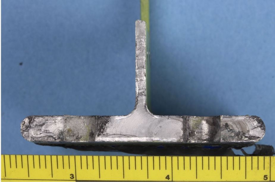
The above photo is from the NTSB investigation. Here are a couple of quotes from “Pilots of America” forum
Hard to see for sure but it looks like at least three fatigue crack initiation sites. Quite a lot of propagation before final failure. You really need striation density counts to know what really happened over the life of the plane. That’s in addition to basic material properties testing.
Second quote – For the benefit of the untrained eye in aircraft structures fatigue, that spar had both classic crack propagation to the degree it was 80 pct through when it ultimate failed, and it also had striations congruent with prior overload (over g). so its not conjecture, the spar reads like a journal of what that airplane went through and it is NOT normal piston aircraft use.
However there are other opinions on the Piper Forum where people say the crack propagation would be very rapid – a bit like a stone chip in toughened glass.
So my question to the very experienced people on this forum is, do people think the areas in the blue circles were pre-existing cracks (I believe the blackened parts are called fretting. Also I have highlighted the area in a red circle which is also possibly pre-existing.
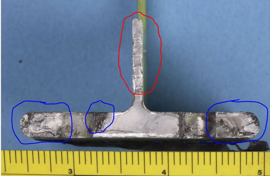
I am assuming the clean break happened on the day of the crash. I am very interested in opinions as I can keep checking my wing spars every 5 hours of flight time. I know I am being totally irrational here, there are far bigger risks. However, if these cracks were visible prior to the accident then there is a way to deal with this through regular inspections until further investigations/ any A.D. comes out.
To me (not a metallurgist, merely a physicist), the red-circled area looks like the oldest damage. The middle blue circle is hard to judge, but it looks like spalling rather than cracking, and seems to extend deeper (in the direction perpendicular to the photo) than the rest.
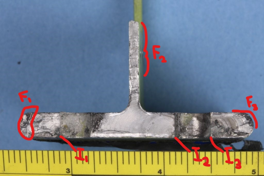
The initiation sites are I1, I2, and I3. The cracks propagate across the material and you can see the beach marks every time the crack opens up a bit more it leaves a line. Once there is very little material left, the part will break rapidly, leaving a different texture. This is called final fracture and I have marked it F1, F2, and F3.
These comments are very generalised and you will need an scanning electron microscope to look at the surface texture to know more. For example, in this case I2 is pretty much text book. I1 and 13 have a lot more texture near the initiation sites, perhaps they occurred under a different stress cycling regime (near the end, but not final fracture?).
Also, you mention the dark area an the left hand side of the central web. This could be fretting (crack surfaces rubbing on each other), but doesn’t really make sense for a crack propagating from I2. It could be a crack that already existed (I don’t think so because I think you can almost see the beach marks from the opposite direction). It also could be dirt or debris from the site of the crash. Cleaning it off (non-destructively) and a lab exam should clarify this. In principle, you might think the dark area occurred first and oxidised (or fretted), but I am not sure what we are seeing here and you would have to examine it properly to know.
Of course I will include caveats, that my thoughts are based less than ideal photos and worth what you paid for them (nothing). There could be more going on (e.g. separate initiation site in the dark area) and larger cyclical overloads from I1, I2, and I3.
To me this looks like a classical fatigue failure. All the lower parts, the flange have fatigue cracks. There are at least three initiated cracks. They have probably come one after the other when the first propagated. The red part is the rest that failed. It somewhat looks that it didn’t fail at once though, but through a series of large cracks.
It will be interesting to read the reason. If it was through overstressing or poor quality material or some other reason.
I pretty much share Canuck’s opinion.
In F2, possibly we see some big jumps before the last failure.
The crack growing from I2 is very clean. NTSB should have no problem counting the striation and getting a crack growth life.
The others might be more tricky
The black triangle the opposite side of the hole from I1 could be a crack in a slightly different plane which stopped for some reason.
About the overstress, a few overstress events do not cause fatigue cracks. If anything, if the crack doesn’t go critical and the section fails during the overstress, it actually stops or slows down the crack because it plastifies the crack tip.
So it’s either repetitive overstressing, bad batch of material, bolts not tighten (,corrosion)
Hopefully the investigation will be able to narrow it down
I wonder, isn’t the position of the initial crack very odd for a bolted connection? With proper torqued bolts there would be very little tension at that location, even when fully loaded. The position of the initial crack is however at the right place if the bolts were not enough torqued, or not torqued at all IMO
There is a tension stress in this cross-section. From the drawing in the other thread the there are 3 other bolt rows. If the joint is correctly designed, around 70/75 % of the total load transfer in the joint is already in tension in the flange. That last pair of bolts add the last 30/25% in bearing (or in practice a fix of bearing and friction).
The stress concentration i.e. the ratio local stress near the hole to the gross stress away from the hole is around 3. The other stress concentration is at the joint between flange and web but it’ll be small (~1.2 at best). So if it cracks it is at the bolt hole.
Thank you all for the replies. This is the internet at it’s best! What is scary is that the initiation cracks i1; i2 an i3 started under the bolt heads so not visible during any inspection.
I also don’t believe that any PA28 “Annual” would normally inspect this area for 3 reasons.
I wonder if the cracks became visible past the bolt heads before failure? I’ll probably keep inspecting this area as at least I feel I’m doing something which might help!
Hopefully the NTSB will keep releasing information as their investigation continues. In the meantime I was out doing a few circuits last night so it’s not going to stop me flying.
All of the cracks seem to have propagated to the side which was visible (although still awkward to get at!) a significant number of cycles before the final fracture regions. This also seems to include the regions which were outside of the surface covered by the bolt head. This suggests that they could have been seen with inspection prior to failure. Unfortunately, we will have to wait until the FAA/Piper establish if there is any thing different about this spar or airframe, if it is likely to occur in others, the time frame for crack growth, etc.
I used to fly a PA28 (with 10,000 hours on it!) and I have never looked at those bolts. Our mechanic was very good and we were watching other cracks (that had been stopped drilled!) but hey ho.
Loosing a wing is a terrifying thought, but by the numbers there must be many tens of thousands of Pipers with this type of wing fastening and it seems incredibly rare that a wing comes off, so I hope it really can’t be that bad.