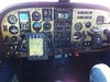
This is what a lot of aircraft have, including mine.
The TB20 has three buses: 1 2 and 3.
Each one powers various bits.
All three come into the radio master switch which contains three relays, so the three buses are still separated when they go to the various avionics.
(Actually the radio master module has a 4th relay which seems to power down the three avionics buses when the starter relay is operated; cars have the same thing, for equipment protection from starter motor spikes).
Looking through the wiring diagrams, it looks like Socata allocated different bits of avionics to different buses according to some "interesting" rules...
BUS1 drives HSI, COM1, NAV1 and the Bose headset power.
BUS2 drives the ADF, DME, stormscope.
BUS3 drives COM2, NAV2, EDM700, and a "graphic computer" which seems to be the GPS+KMD550.
Of course there is a lot of other kit but this is not documented in any readable way as far as I can tell; one has to pull the three bus CBs one at a time and see what goes out...
The transponder is fed via diodes from BUS1 and BUS2 so either of these will power it.
What is interesting is what conventional kit comes off which bus, because if you pull a CB (e.g. to try to stop an electrical fire) you want to know which bits will go out.
BUS1 drives the flaps and the pitot.
BUS2 drives various lights.
BUS3 drives the landing gear.
So if you pull the BUS1 CB, you lose the main "old" navigation gear plus the flaps.
BUS3 will lose the "real" navigation gear and the landing gear.
I have no idea which bus drives the autopilot for example. I have all the PDF manuals but even just finding the autopilot section takes ages, every time I have to look it up. And there are usually several very similar versions of the same circuit, with nothing telling you which one is actually in your plane.
I wonder what rules these people use to think this through.
Sounds like you are ready for a new aircraft.
:-)
You can see the result of a multi bus electrical system with complex rules in the fatal accident of a SR22 in Zurich. Polish IFR pilot thought he was in trouble after one of the two alternators failed, cancelled the safe ILS and got himself killed while trying to manoeuver in marginal VMC close to the ground.
My 1979 TR182 has a very simple electrical system. One alternator, one battery, one main bus and one avionics bus fed from the main bus. Every consumer on the bus is behind a circuit breaker (half of them the old non pullable variant that never triggered in their life and are probably stuck forever).
In my opinion the best way to increase safety is not a super complex and redundant electric system but being prepared to safely conduct the flight without a working electric system. Battery buffered devices, mobile devices, etc. A different situation in G1000 equipped planes of course.
My PFD (Aspen) is battery buffered, 2nd AI vacuum, a handheld radio always on board and an external VHF antenna for the handheld fitted, powerful GPS (Garmin 695) with 6h of battery and an iPad. I would immediately shut down pretty much everything, switch to the handheld radio and save the battery for operating the flaps and flying an ILS if needed.
In order to get a better understanding of where I'd be without alternator, I have bought a ground power unit (GPU) with a digital amp display. This allows me to determine the energy consumption of each individual device on board.
pilot thought he was in trouble after one of the two alternators failed, cancelled the safe ILS and got himself killed while trying to manoeuver in marginal VMC close to the ground.
But why exactly did he do that?
I suppose we will never know, but presumably you can see which systems have gone very easily - or at least with my stuff it is very obvious. Today I have been pulling the three bus CBs one at a time and noting which bits die (which lights in the panel go out, basically).
There is no need to abandon an ILS out of fear. If you are flying towards the localiser and it intercepts (I am assuming that a stressed pilot will simply use the autopilot, which is absolutely the right thing to do) then you are good to carry on. There is no conceivable electrical source failure or bus failure which will give you a LOC intercept but not a GS intercept, if ALT HOLD is working to start with.
Or you could just hand fly it if you are getting the right indications but no autopilot function. An IR holder ought to be able to hand fly an ILS even on a bad day, well enough to get to VMC below. We are not talking about a hand flown OVC002 (or even zero-zero) for which you have to be good.
I suspect the real issue there was the fairly common almost total lack of systems knowledge which is all too common with the more advanced avionics.
Sounds like you are ready for a new aircraft.

No; I would fit one of these. I think we discussed them here before. The problem is that it would definitely be a Major Alteration and given the lack of an airframe specific STC I would be looking at a Field Approval which I don't fancy doing right now (having done two of them in the last 3 years).
In my opinion the best way to increase safety is not a super complex and redundant electric system but being prepared to safely conduct the flight without a working electric system. Battery buffered devices, mobile devices, etc. A different situation in G1000 equipped planes of course.
I disagree, redundancy is clearly the best way to increase safety. However as the Zurich accident shows - just having redundancy is not enough without understanding and training.
There is no way that having a second alternator is anything other than the best way to deal with an alternator failure,
But why exactly did he do that?
Read the report he clearly didn't understand his system. He though he was on battery and was about to have a complete electrical failure.
Slightly off topic...
I had a short circuit in my DA40's battery a few months ago. There's 3 separate busses & the main tie circuit breaker popped in-flight. (the link between the main & battery bus) I reset the breaker once, but it popped again so I left it alone. I was 15 min from my destination airport and landed without incident, but at the time I weren't completely clear on where the error really was & I honestly didn't have a 100% clear picture on how the busses interacted. In-flight is really not the right environment to examine circuit diagrams.
On the ground, examining the circuit diagrams, turns out the best course of action would have been to simply disconnect the battery CB - this would have kept me on the alternator indefinitely while in the air.
Anyway, the day after changing the battery I connected to ground power & spent 2 hrs in the cockpit pulling every conceivable combination of CB (some of which I had no idea what did before I pulled it) just to see how the busses interacted, which avionics connected to what etc. Turns out you can fly with a very minimal set of circuits functioning, as long as you're able to isolate the root error.
Just a tip - first study the circuit diagrams carefully. Then spend a couple of hours in the cockpit on ground power & go through every single CB combination to see the actual effect. I personally felt it was very illuminating...
Can one really run an alternator with the battery disconnected?
I guess it must be installation dependent, because typical car alternator systems need the battery connected for the bus voltage to be stable.
Without the battery you will (AT BEST) get loads of ripple, from the 3 phase rectified alternator output. But it is probably within limits of the avionics...

GAMIs backup alternator modulates the field current dynamically to remove the ripple, but that thing has been just around the corner for several years.
Is there any reason a fairly moderate sized capacitor shouldn't be able to deal with it - at least for the avionics? It works for domestic mains-powered electronics, after all, which are 2-phase and should if anything be more demanding to rectify.
I wonder what rules these people use to think this through.
No official rules, as part 23 aircraft are not even required to have electrics at all, as someone already mentioned above. I would expect that the rules (most probably unwritten!) of the aircraft manufacturers aim for maximum redundancy, even distribution of of the current and optimum (=shortest) cable length.
Can one really run an alternator with the battery disconnected? I guess it must be installation dependent, ...
I depends on the type of voltage regulator - or generator control unit (GCU) as the better ones are called - used. The simple ones need the battery as a sink for smoothing the output voltage. It is not easy to do this with a capacitor alone because of the wide range of currents produced by the generator. In "my" current aircraft this ranges from 300A for a cross-generator-start to less than 30A in cruise flight. Therefore it has quite sophisticated GCUs that would allow in an emergency to power the whole system from one generator alone with the battery disconnected. But then, such a GCU costs a much as a good airworthy C172...