I’m in the process of fitting a new wooden propeller to my aircraft, and have found that the previous crush plate has split and so needs to be replaced. I’m making a new one, but find myself wondering why the old one wasn’t knurled. My thoughts are:
1) Crush plates hold the propeller by friction. Knurling the surface would provide more friction for any given amount of torque than a smooth surface and it would be very easy to do.
2) If the propeller did become loose at all, the knurled surface might ‘sandpaper’ the surface of the propeller more effectively than a smooth surface, breaking it down and leading to problems such as overheating more quickly.
3) The knurling might crush surface fibers of the wood reducing its strength slightly.
There’s also a big heavy steel spacer between the propeller and the prop hub. I’m contemplating making a replacement out of 6082 Aluminium – an easy way to lose the best part of a kilo where I don’t need it. I can see that there are aluminium prop hub spacers available commercially. Do I have to be careful about having Aluminium directly next to the steel prop hub (i.e. corrosion).
Obviously I will be showing the parts to my inspector, but it would be nice to get it all right the first time!
If I understand your hub arrangement, I don’t think much torque gets transmitted between the crush plate and propeller. The main torque transmission must be between the propeller and flange on the hub.
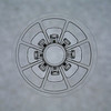
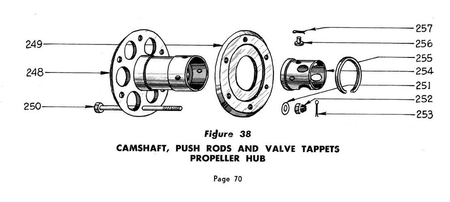
On some engines (e.g. tapered shaft Continentals originally designed for a wooden prop, see prop hub graphic below) it’s common to fit an aluminum propeller in place of the wood propeller on the same hub, in which case serrations on the crush plate pushing against aluminum would achieve nothing.
Does your arrangement look something like this, with Item 249 being the crush plate?
There’s also no need to worry greatly about corrosion between steel hub and aluminum spacers – that’s common practice although I personally wouldn’t worry about 1 kg of weight reduction in relation to the uncertainty associated with changing something important. Do make sure you retorque the prop every so often, as is common practice with wood props. That is important.
I’d be quite interested in finding out why the old crush plate failed, and correcting that issue as first priority.
Thanks Silvaire. I thought’ you’d answer!
It’s similar but much simpler. The propeller is held between two flat plates with 6 bolts. Essentially parts 248, 249 and the bolts. But without the cylindrical central part of 248. I see what you mean about the torque being transmitted from the prop hub rather than the crush plate. Good point.
I’ve seen 8mm crush plates advertised as replacements for 6mm crush plates, on the basis that 6mm ones are apt to crack around the bolt holes – which is what happened to mine. I think the previous propeller bolts had been over-torqued at some point.
kwlf wrote:
I think the previous propeller bolts had been over-torqued at some point.
That would crush the prop, not destroy the plate or the bolts/nuts.
I have never heard the world knurl  but I think I understand what it means from the context. I agree with Silvair. The torque is almost exclusively transfered to the prop via the back plate. The front plateis just a means of getting enough pressure. It should be flat IMO.
With regards to using aluminium in the spacer, I see no problems as long as you use 6061/6082 or similar or better corrosion resistant alloy.
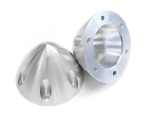
You may also take a look at the crush plates from aeroconversion, formed as small spinners.
When I used to work in engineering, not as an engineer but I drew the pictures, friction was never considered as a means of reacting loads for the reason that it was impossible to quantify. That’s not to say it didn’t exist and perhaps help but it was not relied upon.
So I’d say that what is really transferring the torque is a close fit of the bolts through the propeller. My own machine has little ‘top hat’ shaped, internally threaded bushes which protrude through the drive hub to engage with and transfer the torque to the prop. The prop bolts screw into these bushes. If your machine doesn’t have that feature then the bolts themselves must be doing the work.
You don’t say how the crush plate split, but I’m guessing the bolts got loose, maybe due to the wooden propeller shrinking in dry weather, and the whole assembly twisting and slewing a little about the rotational axis.
There are some protrusions from the propeller hub, but not from the spacer.
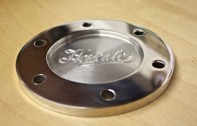
http://www.hercprops.com/2015/02/engraved-propeller-crush-plates-bling-for-your-aeroplane/
mentions warping of the old crush plates as being a reason to replace them with a new propeller. I could imagine that they might fold around the grain.
This thread states that the loads are taken by friction in the torque plates rather than the protrusions:
http://www.vansairforce.com/community/showthread.php?t=90479
I’ll see whether I can get pictures of the damage when I have a moment.
That vansairforce thread mentions a friction face but I don’t think it’s saying that friction is the means of transferring torque.
The cozybuilders link in the third post gives this picture and, apart from the damaged ferrule, my prop boss is similar. It says ferrules, I called them ‘top hat’ bushes.
The Hercules crush plates look lovely, and since yours is aluminium I suppose warping might come into play. Mine is steel, out of sight inside the spinner.
One thing about that Hercules page though. It might just be the photograph but in this image the bolting face looks as though it is slightly dished. Not at all what you want so I suspect it’s the pic.
ChuckGlider wrote:
That vansairforce thread mentions a friction face but I don’t think it’s saying that friction is the means of transferring torque.
It doesn’t matter either way what we call it. The friction forces (when the bolts are correctly torqued) will prevent the prop from moving, even a nano meter, relative to the back plate. Hence friction will transfer all torque. The lugs are nothing more than the safety wire on the bolts in your picture. It’s only there to prevent total disaster IF the torque on the bolts should fail, and also to make it simpler to get the bolts on perpendicular to the plate/prop. The safety wire is only there to prevent the bolt from falling out, it’s the friction between the bolt and the nut, that keeps it in place, and keeps the torque in the bolt.
The friction forces (when the bolts are correctly torqued) will prevent the prop from moving, even a nano meter, relative to the back plate. Hence friction will transfer all torque
Doesn’t that assume that the uppermost layer of the wood of the propeller – a layer of wood of a miniscule thickness and comparable in thickness to any irregularities on the surface of whatever the prop is screwed against – has a sufficient shear strength to withstand not just the average torque but the peak torque pulses from the engine?
If that was true, then gluing the prop to the flange with any glue that is stronger than the wood (e.g. epoxy) would be sufficient – in terms of mechanical strength.
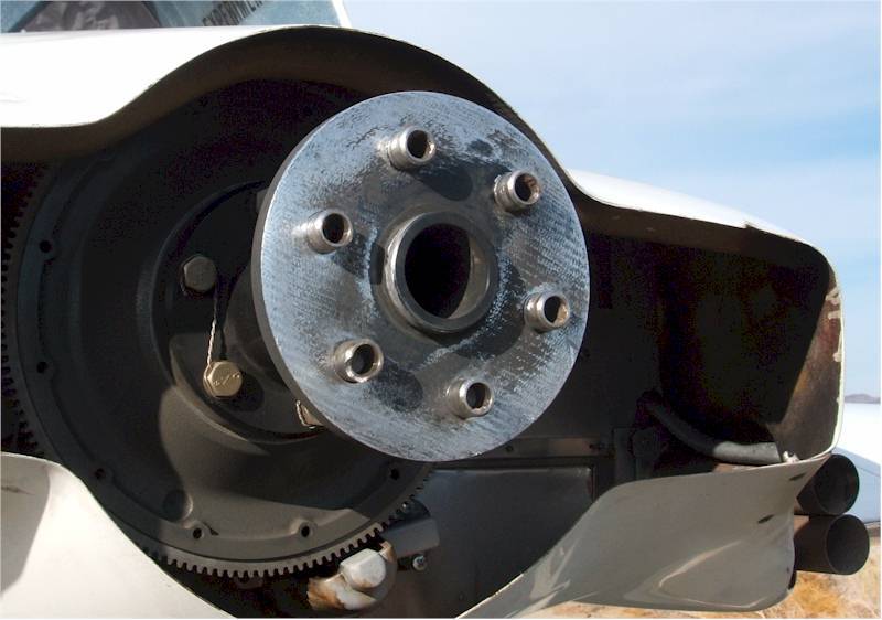
The photo posted by ChuckGlider of the flanged crankshaft shows the ‘modern’ (1950s or so ) design that I believe was implemented by US manufacturers in parallel with metal (instead of wooden) fixed pitch propellers becoming the norm. In this design torque is transmitted by the bushings into counterbores in the prop, or at least this is the ultimate load path – you are not relying on friction by design, even if it does the job in actuality. The ‘early’ prewar Continental hub design that I posted earlier was originally intended for wooden propellers which I assume won’t take the bearing stress of bushings in counterbores so this hub instead transmits the torque by friction, by design, and the shear strength of the wood is sufficient for the job. Otherwise, carrying loads with friction is (I agree) hardly optimal relative to good practice and is why you have to retorque wood props every now and again as the wood varies in size with humidity. How this same hub design works effectively with a hard, smooth, heavy aluminum prop I have often wondered (I own one and look at it every annual), but it does. I think it may have to do with the long prop bolts elongating considerably when torqued and thereby holding consistent load on the friction surface between the prop and hub.
In spite of the above I have an appreciation for the early hub design because like many old technologies it has features that got cut out of later designs to reduce cost: The prop hub is removable from the crankshaft and in the event of a prop strike, particularly with a wooden prop, it is very rare that anything happens to the crankshaft. Normally the worst case is that you replace the hub and propeller and almost nobody stripped these engines after a prop strike. Also, the design is clever in that removing and installing the propeller requires only a long steel bar and the hub has two threads, one of which allows the hub to function as a puller to extract the prop off the crankshaft taper. Finally, with a quickly removable hub and propeller the cowling doesn’t have to be split (you just remove the prop quickly, no bolts, then pull the cowling off the front to remove it) and the front crankshaft seal doesn’t have to be stretched over the flange before installation. It’s a neat design in its own way, for low powered engines.