
Peter,
At present, the following two options are used with Motorcycles:
Option 1 : Serial Regulator: This is how the Ducati Energia and Silent Hektik work (Note : single phase alternator used in the ROTAX 912, not a 3 Phase alternator)
Original GB patent: 1982 (patent applied for 1977! most likely developed early 1970’s.).
Option 2 : Shunt regulator : This is how many Jap regulators (Shingenden FH012AA, FH020AA Work) work (employing MOSFETS) ; Hard for the alternator, because it always runs at high loads. Hence lot of problems (burnt alternators) still recently with 500W 3Phase Suzuki Bikes..
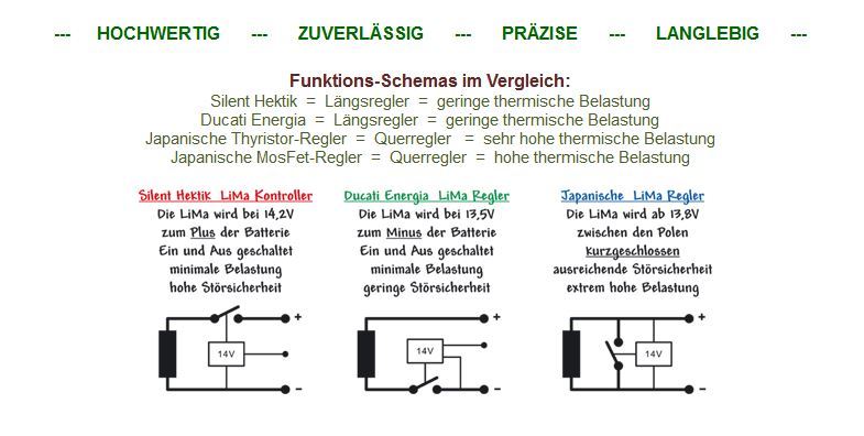
As a result both Shingenden and Ducati Energia have recently developed much more sophisticated serial regulators (eg. Shingenden SH840):
These are the ones I would use on a ROTAX 912 powered plane, if I would have to make the choice.
BTW
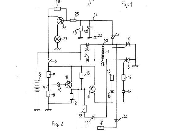
The ignition you are referring to is a CDI or Thyristor ignition (where a SCR or Thyristor discharges a charged (to 300V DC) Capacitor into an ignition coil).
This employs a High Voltage, but low current Thyristor.
It was indeed used on a lot of Jap bikes in the 1970’s.
The LUCAS RITA (late 1960’s) was a Transistor ignition, in which a Bipolar Transistor is used to switch the primary of the ignition Coil.
The LUCAS RITA used a BU941 (Motorola Darlington (400v 15A), so indeed these semiconductors existed in the 1970’s (albeit at a price!!)
Also high power high voltage SCR’s existed in the 1970’s but at that time were not really suited for a PWM regulator. (extremely high price).
Hence, presumably LUCAS came up with the idea of simply shunting the rectified AC by one low Voltage (14V) Hi Power zener diode:
Crude, but it was OK and much more reliable than the DC dynamo’s in those days with their brushes and mechanical regulating boxes.
Available technology has always to be compared with its price (it has to be viable for the car manufacturer, who tries to skimp on every bolt).
However, If you get it wrong, like the British Motorcycle and Car industry, you will loose your customers.
But it is my personal opinion that for a Private Plane, I would not skimp on some money, but go for the Best.
At present, that seems to be the SHINGENDEN FH840 (serial regulator), which is also available as Suzuki OEM for some US$ 180.-

http://roadstercycle.com/#SH847_SERIES_RR_KITS_ARE_NOW_AVAILABLE_
http://www.superhawkforum.com/forums/modifications-performance-29/sh847-series-r-r-34077/
But I don’t think regulator this has applied on a ROTAX 912 engine, yet
Regards,
Martin
Hmmm, interesting – thanks.
Single phase output means the rectified output voltage falls to zero between cycles, so a “capacitor” (a battery) has to be always connected. It also means you cannot generate DC properly, without a whacking big capacitor on the output of the rectifier (which will incidentally hammer the rectifier diodes).
If you feed the single phase rectified/PWMd stuff into a battery, you will get ripple on the output bus, of the peak current times the battery internal impedance, so you will never have decent smooth DC for avionics.
So the Rotax solution is horrible.
I accept that the motor trade does everything absolutely minimally, subject to it not blowing up before the warranty expires, but power transistors have been around for years and don’t cost much. I used the 2N3055 (and some germanium versions) in Czechoslovakia in 1968 or so. In the mid 1970s I was building 500W per channel stereo power amps with 0.01% THD and +/-80V supply rails, using ten 2N5239s per output amp, and we used those only for the high voltage and the good secondary breakdown curves. In the early 1980s I was using VNE003 mosfets (to PWM drive 24V DC motors for winding film for projectors, with a precisely controlled torque) which were pretty big (no data sheet exists online) so even that is nothing new.
So I think these designers are simply dumb.
An absolute give-away clue to stupidity is putting a zener in series with the base of a transistor

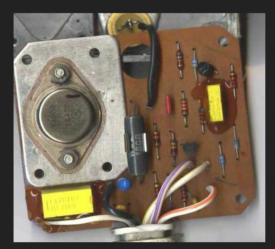
which will make its current (and its temp coefficient) vary over a big range according to the transistor current gain, so the regulated voltage will be all over the place. Also that PCB picture, especially with the power resistor mounted like that, is something made in a garden shed. It’s really horrible.
There ought to be an aftermarket for decent regulators, because even motorbikes cost of the order of 10k.
Hi Peter,
Fully agree. (but do remember that at normal RPM the frequency is much higher that at home (typically 700-1000 Hz, not 50 or 60 Hz.
But could you please also comment on the latest 3 Phase Shingenden MOSFET Series regulator: (SH847) ??
I attach herewith a link to their Patent Application EP2362535A1
https://worldwide.espacenet.com/publicationDetails/originalDocument?CC=EP&NR=2362535A1&KC=A1&FT=D&ND=3&date=20110831&DB=EPODOC&locale=en_EP#
BTW It is not the Motorcycle Maufacturers who design these things but the Service Industry (Bosch, Nippon Denso (Lucas , Magneti Marelli) etc.
LUCAS also made products for the space industry, so that makes you wonder!!
(normally Motorcycle manufacturers have no clue of these things and choose the cheapest option).
Even worse, sometimes a good design is made worse by an improper installation due to ignorance of the Electricians of the Motorcycle Manufacturers (omitting ground wires, employing too thin wires and bad connectors, omitting fuses, relays of insufficient power etc. . Moto Guzzi was/is very good at that.
But I would be eager to hear from you whether you think if the “novel” Singenden SH847 MOSFET serial reguator would be a good alternative for Jan’s Ducati Energia RR Or the Silent Hektik R4112 or the Schicke GR6, when applied to his ROTAX 912 engine (250W single phase alternator).
Looking forward to an assessment / opinion!
Regards,
Martin
The application shows nothing which isn’t obvious. It shows a 3 phase alternator, with a PWM rectifier feeding the battery, and some control circuitry.
I can see only one page.
I wonder what they might have patented? It might be a purely diversionary patent… I did that once, in 1991 
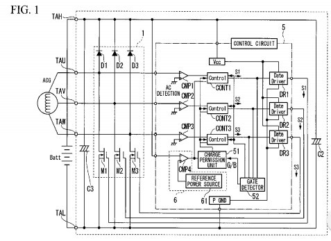
Sure; the ripple frequency is higher but the ripple voltage will still be pretty awful with a single phase system. With a 3 phase system the output never falls to zero (or anywhere near zero) so it is possible to PWM-generate clean DC without using any storage components, apart from a capacitor to smooth out the PWM output.
The GAMI Supplenator claimed to do just that. No need for a battery to get clean DC. Very old technology – 1970s or earlier.
Hi Peter,
On the request of Jan Olieslagers I have benchtested the Schicke GR6 regulator as well:
My conclusions:
Properties:
A) Serial Regulator with a Set Point of 14.1V on the Vsense (thin Red Wire) connection. (however this is adjustable with a trimmer (mini pot)).
1. Reasonable friendly for the Alternator coils (serial regulator principle = DUCATI ENERGIA principle: GB 2 016 750A)
2. Except if load is very low or no load: High Input Voltage → Shunting of the Regulator Input: Extra feature to the Ducati Design
B) Regulator itself is protected against loosing the connection between B+(thick red wire) and the Battery: However, the subsequent electrical users are certainly NOT PROTECTED because the output voltage will increase dramatically (this situation will e.g. occur if the battery will suddenly demonstrate an open cel (during the flight).
C) Protected against loose connection of Vsense (Regulator will switch off, if there is no voltage on Vsense).
D) Not protected against a shortcircuited cell (Plane could most likely not be started) but might be not detected if Jump Wires and an external battery would be used.
D) Cannot be used without a battery.
An extra electrolytic condenser (C: 22,000 µF, 75V) at the regulator output had no stabilising effect on the output voltage.
Increasing voltage WILL damage instruments.
Advantages
Reasonable mechanical construction.
Regulates output voltage reasonably to 14.5-14.6 V (Semi Steady State); however very slow regulation (hence requires a larger battery than the 12V 4 AH gel battery tested).
Output voltage is not optimal for Gel batteries: potential gas formation; overpressures, discharge via safety vent; (however can be adjusted to a lower voltage with TrimPot).
Do not use with LiFePO4 Batteries without protection utility against high voltages!
Regulator is reasonably protected against self destruction (High Currents and high Input Voltages).
Regulator itself is protected against a lost connection between Regulator and Battery.
(High Input Voltages to some zo’n 50 V ~ AC 50Hz tested; possibly immune against 100V AC @ 800 Hz: maximum voltage Rotax Alternator) → shunting from some 22V~ input voltage occurs)
“Relatively low loading of the Alternator Coils compared to pure shunt regulators like Elektrex World RR51 (or bv Shingenden FH020AA/ FH012AA).
Good track record in Rotax 912 installations where the Ducati Energia Regulator failed due to improper installation (insufficient cooling).
However, also this regulator requires forced cooling in an airstream for the nominal output (250W) of the Rotax Alternator!!
(same comment for the original Ducati Energia and the Silent Hektik R4112): most regulator failures are due to improper wiring and improper cooling.
Disadvantages
Too thin wires (however silicone rubber insulation: good); mediocre Faston connectors (under designed): same comment for Ducati Energia (hardwiring suggested, omitting the connectors) and Silent Hektik (use R4112 version).
NOT PROTECTED against a malfunctioning battery during the flight (open cell or short circuited cell).
(Selfstarting (with or without capacitor; C 22000 uF 75V used in test); Output voltage keeps on contimuously increasing if connection to battery is disconnected (e.g internal open cell during flight).: will destroy the Instruments if these are not protected by an Overvoltage protection Circuit (NB Schicke markets a suitable protection device).
Not so efficient: still dissipates relatively much power at low power offtakes (and hence high input voltages).
Heatsink still relatively small: requires forced cooling for max nominal output regulator: (250W); Certainly not suitable for installation behind a Dash.
(Regulator is lukewarm (steady state) for offtakes of some 70W but already reasonably hot (60- 70 deg) . C for 120W offtake!!
NB maximum power 250W even not tested in view of high temperatures!.
Recommendation: Only use with cooling by Natural Convection for loads to some 70W.
No thermal protection of regulator (>70 graden C).
Reasonable price.
Disclaimer
These are my personal measurements and opinions; No rights can be obtained/claimed from the above statements!!
@ Peter.
The picture of the circuitboard is of a Lucas Rita Electronic ignition.(later version had an epoxy board).
Do not agree with your comment re a Garden Shed construction
(The board itself is installed in a very ruggedised Aluminum box. ). Failures were only due to users shortcircuiting the output.
(can be repaired by exchanging the Darlington Transistor) (not cast in epoxy).
This ignition was very reliable and was used in fact in 3 Monte Carlo Rally victories..
The only weak point was the connector between the magnetic pick up (the reluctor) and the box.(can of course be improved0.
Was really State of the Art in the late 1960’s and standard installation on 1970’s Triumph / Norton Commando motorcycles.
Cheers ,
Martin
I had a virtual heart attack when the first Ducatti regulator failed while flying a Rotax powered AeroSpool WT9. A full glass cockpit added to my stress. Luckily the backup battery in the PFD held up until I had airfield in sight and I did not need to do the job with ASI and compass! It had lasted 15 or 16 months (in cool Latvia). Obviously I replaced the regulator with an identical one. When that too failed at about 15 months I was a bit annoyed. Out came the research hat and the result was a shiny Silent Hektik regulator installed. It was perfect. Rock steady 14.1v and I could not break it with multiple trips to Sicily (OAT 28C) It was still working fine when I sold it 41 months later.
In conclusion, glad to be on the same side as the Germans with their super engineering. More worrying is how Rotax supplied so many obviously inadequate components over the years.
Hello folks, on a similar note.
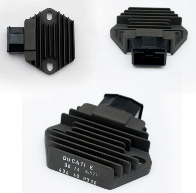
ULPower use a 3 phase stator and what looks to be an SCR thyristor based shunt RR. Ducati Energia 434 40 0300 rated at 30A.
http://ulpower.news/rectifier-regulator-hints-n-tips
These expose us to overheating risk and often fail, not to mention non water proof connectors etc.
ULPower also sell a 50A mosfet based RR but I am not sure if it has a series or shunt based regulator.
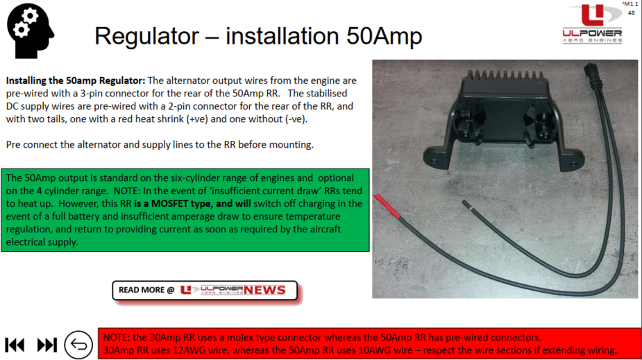
Looks like it is something like this from a Harley.
https://ricksmotorsportelectrics.com/New-OEM-Style-Rectifier-Regulator-10_902B
Has anyone used one of the above recommended Shingenden series based RRs (SH775 35A or SH847 50A) in an aircraft so far? I am concerned about RF interference with radios and such from the higher frequency switching of the series based regulators but keen to get rid of the shunt based regulator to de load the stator.
Assuming the FH020 has a shunt based regulator.

