
The capacitance of the fuel sensor varies with the permittivity of the dielectric. I think permittivity will alter with density, so a capacitive fuel measurement will essentially be a mass measurement.
I thought GA capacitive fuel gauges contain a number of capacitor elements and as the fuel level rises it appears in proximity to more and more of these elements. I don’t think those gauges contain just the two “plates” of a classical capacitor.
Alternatively, they have two elements but the dielectric (the fuel) has such a high permittivity that the capacitance seen (for any given fuel level) is determined almost totally by the permittivity of the plastic moulding of the fuel level sensor. Then the capacitance is directly proportional to the fuel level. But there needs to be some sort of cable compensation too.
Also, a tank with a dihedral needs more than one sensor.
In a normal world having more than a single 20usd sensor per tank on a 700k usd plane should be a given.
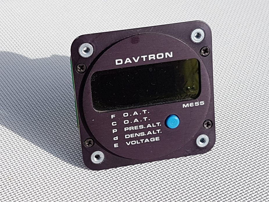
Following on from this thread I thought it would be fun to have a thread showing what is inside various bits of avionics 
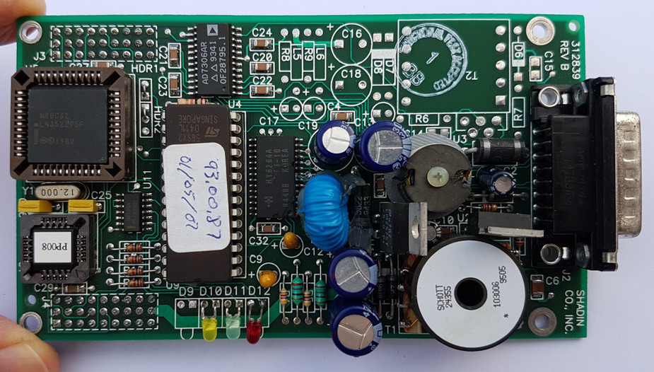
Here is a Davtron 655
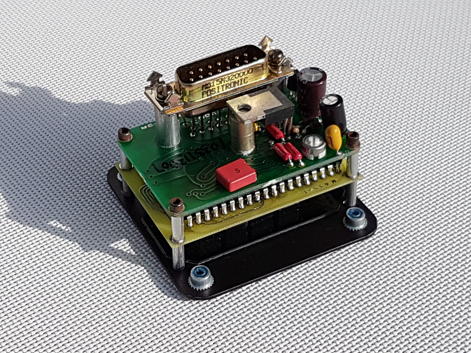

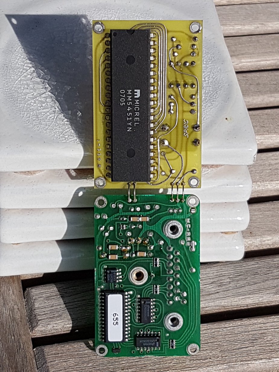
The big chip is a dumb LED driver, so all the display decoding is done in software.
The micro is the one with the label on it. It is a PIC14000-041.
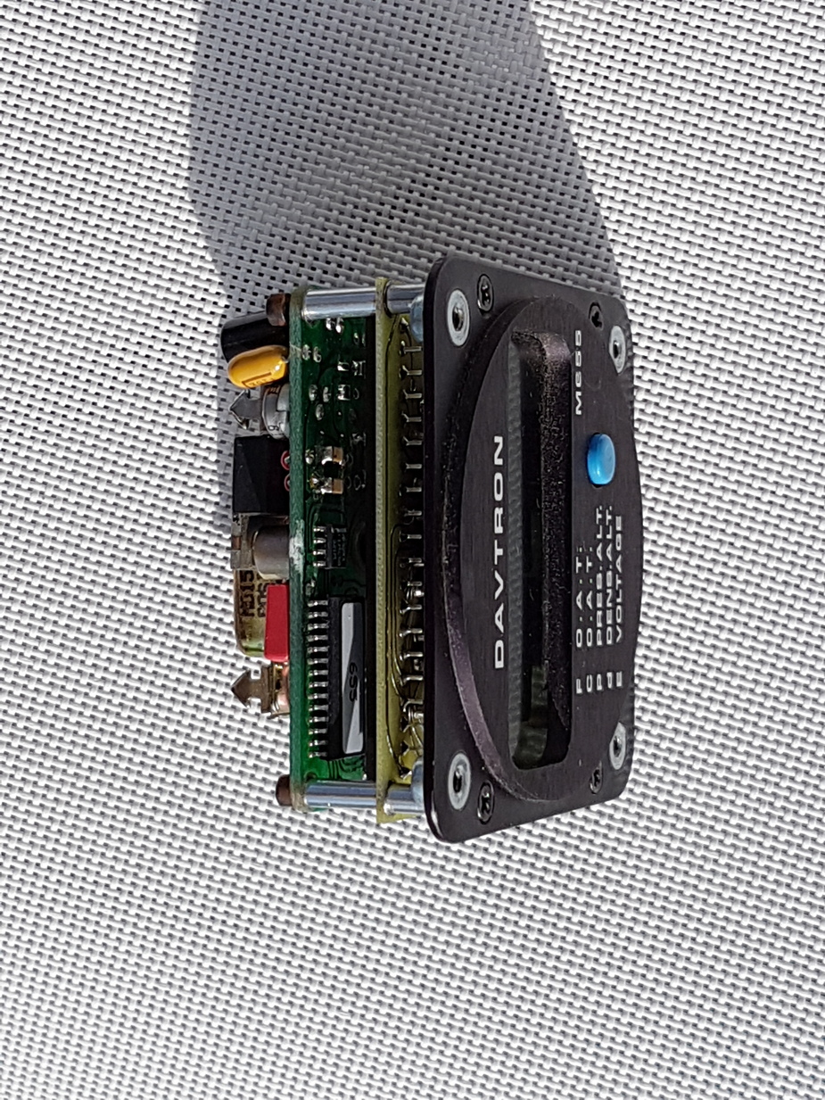
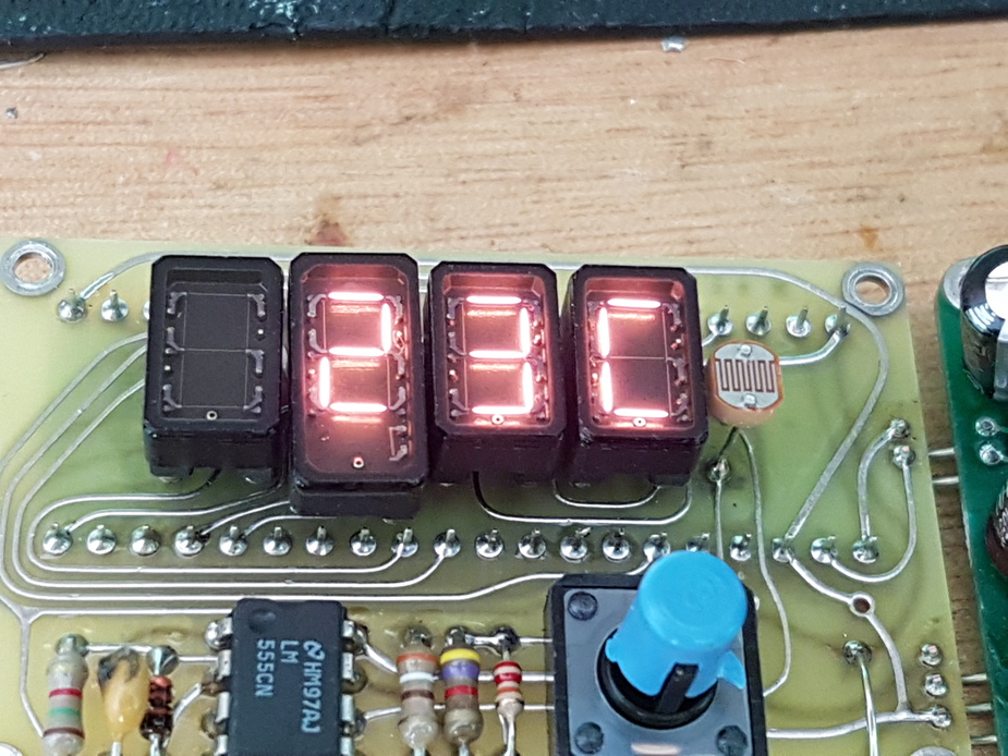
The displays I have never seen before. They look a bit like the fluorescent ones in the King radios. They are marked KW-1050 58774 and nothing comes up on google. However a very close look shows these to be incandescent filament lamps! Like the early 1970s calculators.
There is no external A-D converter but the PIC contains a slow 16-bit one.
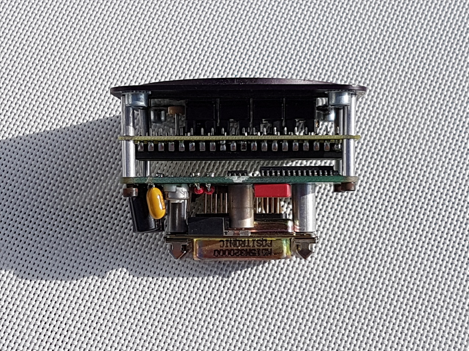
The linear regulator is a 7808 and at 28V that will be dissipating the entire display current x 20V which is (80-110mA according to display brightness) up to 3W! It is bolted to the back of the aluminium case.
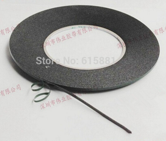
The PCBs are from the 1970s, pre-CAD and done with the black adhesive tape, then photographed… The whole thing is a trip back in time, about 40 years, but the PIC is obviously more recent.
Parts cost? $30 or so, including a few $ for the fabricated case. But I can only guess the cost of those displays. It goes for $280
What a weird blend of old and (relatively) new.
That unit now has LED displays but they still sell the old filament based one for use with night vision goggles.
What I found truly amazing is that they are still doing their PCB design using the black tape. The CPU board is done that way too!
The whole world went to CAD (Orcad, Protel, etc) about 25 years ago.
It’s probably the same bloke working there!
From this thread here is the Shadin ADC-200 airdata computer
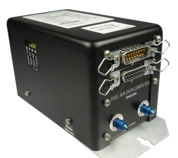
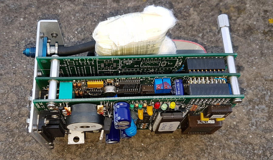
The processor is an 8032
The second PCB has various analog bits
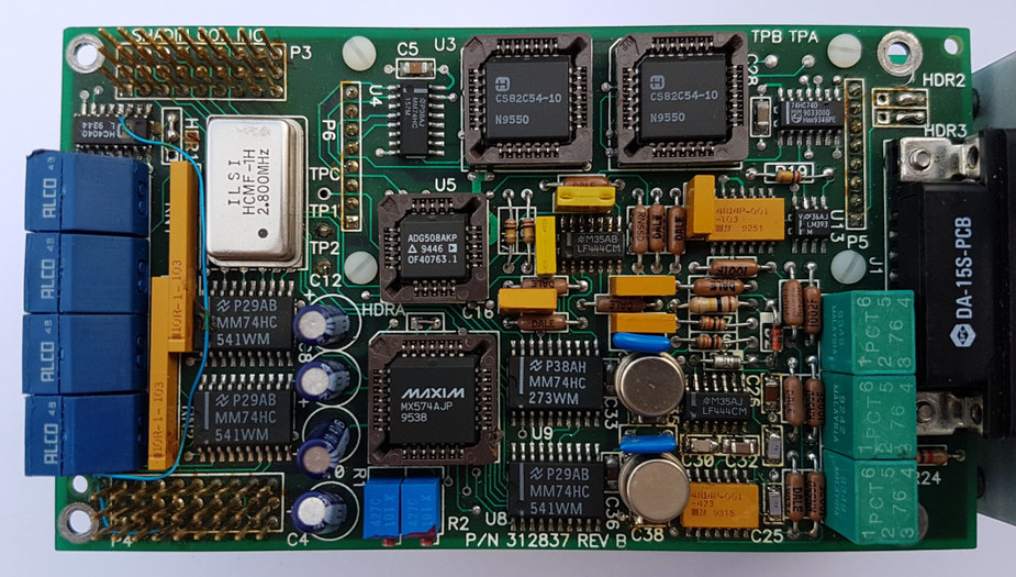
Various date codes on components suggest it was made in 1995.
The differential pressure transducer appears to have its own heater to avoid having to temperature compensate it against ambient
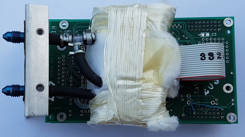
It is a tour de force in how to make something unreliable in an aircraft… all those tall components
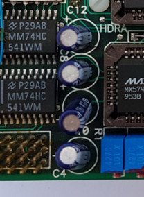
which not only break off under vibration but, being electrolytic capacitors, will age and lose their capacitance.
Peter wrote:
It is a tour de force in how to make something unreliable in an aircraft
And now imagine the same kind of technology used in an [ostensibly crash-survivable] FDR of a military aircraft. Here are the post-crash innards of one from a Russian Su-24 shot down by Turkey for briefly entering the Turkish airspace from Syria:
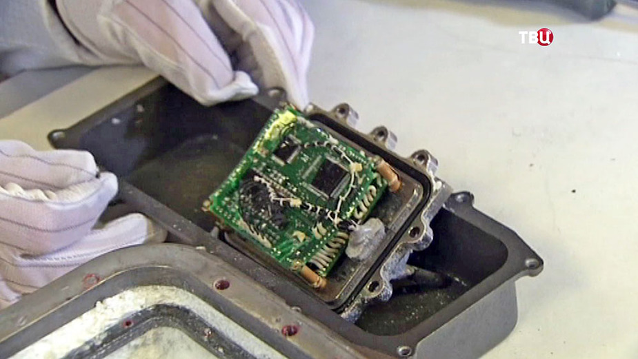
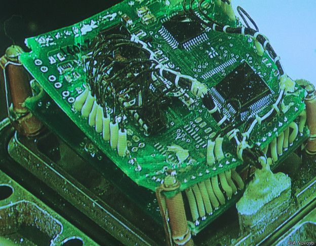
Well at least it is largely surface mount, though the mounting pillars are flimsy as hell. Whoever did that had no clue at all.
In 1991 I did a project for a towed array sonar (for oil exploration, not military submarine stuff) where compressed air was used to create shock waves, which propagated through the sea bed and were picked up by the towed array, for later analysis when the ship returned (the ship operator was not supposed to see the analysis  ). The assembly had to withstand something like 1000G. The CPU was an H8/500. It was on 2.5mm fibreglass, well supported, and all SMT. No component was more than about 3mm tall. Back then there were no issues with getting the components and today it is trivial. Nobody needs to use electrolytic capacitors, and everybody has known for many decades that they have a limited life – unless you get specialised milspec ones. Large cap values can be eliminated by design.
I thought military aircraft don’t have FDRs – for obvious reasons.


