
Many thanks for posting that, Flyer59. Pointing out that it is a link to a pay forum would be a lot better.
That’s really good info because I have a similar system.
However I see some incorrect info there – no doubt emanating from some installation manual written by someone who knew almost nothing about electronics. The 20milliohm value is almost meaningless because what matters is the RF impedance, not the DC resistance. I saw the installer of my system make the same mistake. Firstly they ignored the Socata ground plane inside the composite roof (because they could not be bothered to machine down the upper surface where the antenna would mount, to reach the ground plane) and then they stuck their own self-adhesive stuff underneath and connected that to the airframe with a piece of wire, proudly telling me it was x milliohms, not realising that’s irrelevant at the ~1GHz RF frequency. The inductance of that wire would be many ohms in reality. One cannot check antenna matching with a DC resistance reading. What probably saved the day was the two lengths of RG400 whose thick double shields ran continuously from the Avidyne 605 box to the new ground plane… Plus the capacitance between the new ground plane and the one buried inside the composite, which over the large area I estimated at a few thousand pF which is a near short circuit at 1GHz… so they got away with it.
What is true is that if the resistance measures at say 10 ohms, then you definitely have a poor connection. But 20 mohm versus 5 or 100 is almost meaningless.
That said, I do get disappearing targets but I believe it is caused by airframe masking coupled in some cases with poor transponder installations in the other aircraft. Bizjet (and above) targets never do that. But plenty of 30 year old GA ones do, and some are not visible even head-on till they are 1nm away. I think my antennae are too far back and are partly shielded by the curving cockpit, both above and below.
It’s interesting that a disconnected antenna blows up the unit. That’s not such a good design!
Peter,
Avionik Straubing does not believe that a bad antenna connection could ruin the unit. Some folks at COPA wrote that bad grounding would “overheat” the processor. Is that possible? Pretty important for me, because I don’t want to spend $ 4 K and then risk another failure …
I never got disappearing targets, by the way, the unit would only go offline and if I reset the CB it would work another minute or two… and the same thing would happen again. But then on other days I had no failure!
I have only one antenna on top, but I had the feeling that the system shows all transponders. But i am not sure.
The loaner unit works perfectly, I’ll test it again tomorrow… if the weather is flyable.
Some folks at COPA wrote that bad grounding would “overheat” the processor. Is that possible?
Not so much as bad ground but a bad connection to the antenna, yes. Either the signal or the ground not being connected would cause a problem.
Also I don’t think it is overheating. A disconnected antenna causes a situation where the output stage can get damaged by poor load impedance matching (VSWR). This is potentially true for any RF transmitter of significant power. In the late 1960s I used to build pirate radio transmitters (~500W, 2×807 valves which used to glow red hot; somebody even powered them from the 700V DC supply of a railway track  ).
).
Jesse here knows much more about RF than I do.
I have only one antenna on top
How does that work, to give you azimuth?
Flyer59
If I may be forgiven for offering this advice on this forum: I suggest it might be useful for you to talk to Dave Fetherstone at Nexair Avionics in the US. I understand that he is very knowledgeable and I think he would be happy to talk to you about these issues. His contact details are available on COPA. I won’t post a link as I don’t want to give further offence.
Thank you Jonzarno, I will send Dave an eMail!
all the best
Alexis
How does that work, to give you azimuth?
I really have no idea, Peter, I am just a stupid user :-) I can change brake pads or even take an engine apart and back together (but have done so only with car engines) but electronics are really not a field I know much about :-)
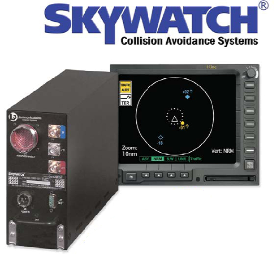
I guess the L3 497 Skywatch page has the explanation.
The other day I talked about both the TAS 600 and the 497 Skywatch with Avionik Straubing. They said that in their experience there’s not a big difference between these two systems and that the Skywatch works just aswell. In certain situations (head on, target below and not too far away) the TAS 600 will see a target where the Skywatch might be “blind” for some seconds. But that’s just stuff I heard, i really don’t know.
The antenna ground connection must be 20 MILIOHMS or less!
This seems highly dubious. If that was true, you could very easily destroy the unit by wielding a screwdriver (or other metallic object) close to the antenna while the unit was transmitting. Or a piece of ice sticking to the antenna would do the same.
Does your avionics shop have a miliohm meter?
Hopefully. How else are they going to check the ground straps of the trays? 20 Milliohms can make a difference in the starter path or during a direct lightning hit, but I cannot imagine any other place they would make a difference.
When there is a poor ground, the transmitter will be mismatched to the antenna. So it will cause the transmitter to heat up,
There is some truth to it. Although for that to happen noticeably, the antenna ground connection would have to be in the 20 ohms order, not milliohms!
Furthermore, the transmitter will have an efficiency of at most 50%. So in the worst case (completely broken off antenna, or a full short circuit in the cable), the additional power (and only if the transmitter doesn’t throttle back – most would), would only be 50% of what it dissipates anyway. If that caused a thermal shut down (or even worse run away), then the design was marginal to start with.
So again, anything less than a few ohms won’t cause any noticeable increase in transmitter temperature or any other problem unless the design is crap.
I second the recommendation for Dave at Nexair. He has done a lot of work for me and is very helpful. His pricing is also very competitive.
I would like to know how it gets the azimuth with just one antenna.
How many cables go into the antenna?
A google/images on it shows three RF cables. Do all three go into the bottom of the single antenna? Maybe it has 3 blades, all in one moulding. The TAS60x single antenna contains two blades, one in front of the other. The dual antenna contains two blades too but you can see them separately.
Dave Fetherston from NEXAIR Avionics in Massachusetts/USA offered me an exchange unit for $ 2000!
I wrote to Dave yesterday and he replied this morning.
Looks like another company I would recommend!
Thanks for that tipp, guys – looks like this will save me $ 2000 !


