I have some info from a TB20 owner on the installation of the CIES / Aerospace Logic gauges. This is the pre-GT model; the GT has accurate (capacitive) fuel gauges and doesn’t need this.
Here is a composite of the information he sent me:
Photo1 shows the gauges in operation during flight.
We really like the “annunciator” effect when the bars (and text) change colour if any paramater is outside the normal range. This photo also shows how we have removed the original engine/fuel gauges and replaced it with a laser-cut auxilliary panel containing the fuel flow computer, etc..
We are very, very pleased with the kit in operation. The gauges themselves and the displays are very high quality and the brightness can easily be adjusted via the buttons. We did wire it into the dimmer circuit but the dimmer sense is the wrong way around. The aircraft dimmers start fully bright and dim as you turn the knob. But when connected to the Aerospace Logic gauges, they start fully dim and get brighter as you twist the knob. And we did not want to bother with adding a separate dedicated dimmer control for the Aerospace Logic gauges. However, we are going to fit one of their multi-cylinder CHT/EGT gauges and I am going to get my night rating soon so I suspect we will add a dedicated dimmer at some stage.
Photo two shows the gauges with the engine stopped and the master switch on.
Voltage is green because I am hooked up to external power. Oil temp. is amber showing ambient temperature. Oil pressure is zero and red because the engine is stopped. Alternator load is red showing a fault because the engine (alternator) is not running. It would also look like this if you switched off the alternator field. This is
I would be happy to share much more with anybody that is interested. I have detailed photos and wiring diagrams and a full parts list for wires and connectors.
I understand that CiES got the mounting hole dimensions by measurements from an old sender. If that is the case, I am not surprised at the fit-up problem. I have recommended to CiES that they contact Daher and get the actual manufacturing dimensions for the mounting holes on the tank. I have not heard back from them but I think I will make a follow up enquiry. It is obvious that everybody is having this problem and I think that is an unacceptable quality failure. The gasket also needs
The CiES senders are beautifully made, as are the Aerospace Logic gauges.
I just heard back from CiES. They have about 100 sender casings manufactured for the TB series.
They have obtained a second Socata resistive sender and have measured it again.
As a result, they are modifying the mounting holes on the 100 TB series casings they have in stock and are hopig this will solve the fit-up problem.
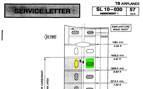
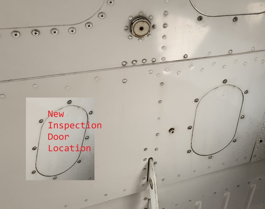
There were significant issues with access, to install the senders. One needs to install an additional inspection panel (per wing, obviously).
the installation was quite difficult and I have passed all my observations to CiES.
Both CiES and Aerospace Logic were prompt and helpful with our installation queries.
Calibration observation
We did notice that there appears to be a dead or near dead zone at about the halfway mark in each tank. It appears that the inner sender float reaches the upper limit of its travel when the outer sender float is either not yet floating or only just floating. There does not appear to be a significant operating overlap between the floats. We just carried on with the calibration process and everything was fine. Perhaps this means the gauges may “jump” a little when the fuel is at this particular level in each tank but I guess that does not matter.
Problem 1
It is necessary to disconnect the aileron operating tube at each end (inboard and outboard) to get proper access to the senders.
Also, for the inboard senders, we found it easier to have the aircraft jacked up so we could retract the main gear to further improve access.
Problem 2
We have suggested to CiES that they check with Daher on the correct dimensions for the mounting holes and that they increase the OD of the mounting flange but we have not heard back from CiES to date.
To make the installation easier, we cut the heads off three of the old sender mounting screws and used them as studs to assist in getting the new sender in place. The old mounting screws are much longer than the new ones you will need to get and they act as a guide to get the new sender in position. We then removed the first stud and replaced it with the new mounting screw. This was repeated for studs 2 and 3. This was of great assistance in the installation of the inner senders in particular.
Problem 3
We were careful to tighten the three new mounting screws evenly and not to over-torque them. We have had no leaks to date.
Engine gauge
Because we have a legacy type panel, with no glass panels, the Aerospace Logic gauges fit in well with the original panel design. We have now ordered the Aerospace Logic multi-cylinder CHT/EGT gauge and hope to install this before the end of the year.
However, like many other owners, I had a lot of difficulty with the mechanical installation of the senders and had to slightly enlarge the mounting holes on the sender flanges with a file.
I sent my installation feedback and photographs to CiES and they advised me last week that they have done further investigations with another one of the original Socata (Peugeot?) senders. As a result, CiES are now modifying the mounting holes on the 100 TB-type sender casings they have in stock. This should solve the problem with the difficult fit-up of the new sender.
The green door shown here is the one which needs installing
Here is a mockup pic
If anyone needs to know more, feel free to contact me and I can put you in touch with the TB20 owner who did this installation.