I don’t like the idea of a forward facing filter – it leaves you exposed to impact ice blockage and very reliant on a functioning alt air door.
FWIW, I have never seen any blockage of the air filter intake – not even in what must have been severe icing conditions of ice accretion of the order of 1cm per minute.
OTOH I was using prop TKS then, which kept the front window clear (amazingly, considering the thin fluid deposition corresponding to ~ 1 litre per hour and that’s covering several square metres of area) and the air filter intake gets the pro-rata share of that.
I have never flown in airframe icing conditions without the prop TKS.
I don’t know the formula for engine efficiency based on the delta-T from the intake to the exhaust, but a 20K delta (which is about 7% of the absolute temperature) must have a huge effect. And at/near the operating ceiling, by definition that must be a big performance hit. There is no free lunch… if you want the inlet to the fuel servo (or the carburettor venturi) to be above 0C, even at ~FL200-250, you have to pay the price in efficiency. A turbo obviously helps a lot but a turbo won’t help with the engine efficiency. You will have the required MP but will be pouring in more fuel.
Peter wrote:
A turbo obviously helps a lot but a turbo won’t help with the engine efficiency. You will have the required MP but will be pouring in more fuel.
Yes, best is to drive your car at 60kph on the motorway and fly your aircraft at 40% BHP 
Re the NACA inlet and icing (sorry for belated reply) – see www.dtic.mil/cgi-bin/GetTRDoc?AD=ADA801284
Quoting from the study (the under-cowl scoop is the early version of what is now known as the NACA scoop):
aerodynamic surveys indicate that an under-cowling scoop of the type investigated in these tests can achieve ram-pressure recovery comparable with that of the standard scoop. The results of the rain-Ingestion tests indicate that the under-cowling-type scoop ingests less than 5 percent of the free water in the air entering the induction system as compared with the standard scoop. The icing of the carburetor screen with the under-cowling scoop was negligible; whereas with the standard scoop it was excessive.As shown in figure 5, the under-cowling scoop is designed to protect the duct inlet from the direct ingestion of free water. Water separation by the under-cowling scoop depends on the relatively great inertia of the water droplets, which causes the droplets to continue in substantially straight-line paths while the charge air curves sharply into the scoop. A theoretical analysis of the inertia-separation principle as applied to the under-cowling scoop is presented in the appendix.[/quote]
Mooney solved the intake icing problem on the high flying J by using a NACA intake scoop.
Also there are no reports of the SR22T fuel servo icing up because (as previously discussed) the alternate air box is upstream of the intakes….
Does inertial separation work for supercooled water droplets?
I can see it will work for rain.
How are rain droplets different from supercooled water droplets?
Size… rain droplets fall down as, ahem, rain, but SLDs are much smaller and just float around with the air.
What makes them not fall down I have no idea.
Per the FAA SLDs are 500x larger in diameter than the droplets encountered in cumulus or stratus type clouds (i.e. the ones that float around) and have far larger inertia so (in theory) an inertial separator should work, and (in practice) it worked on the M20J high altitude tests.
From: http://www.mooneypilots.com/mapalog/M20K252_evaluation_report.htm
[quote]
The next big change with the engine installation was a redesign of the 231’s primary induction system. The 231 has a complex and relatively inefficient duct arrangement mounted on the copilot side of the engine. From flight testing, we knew it was inefficient, choking air being delivered to the compressor. Second, it was prone to allowing ice particles to enter the inlet duct and collect on the face of the induction air filter. A side mounted NACA duct and filter can arrangement was designed and tested that was non-icing and that delivered lots of induction air to the compressor. What a great change! The TSIO-360 in the Mooney now had plenty of induction air to breath and use for combustion.
[/quote]
Having dropped the bottom cowl of the Ovation, I looked closely at the induction – air gets into the filter canister via a front naca scoop under the prop, and exists to the sides and turns 90 degrees again to the front and then upwards around the prop hub. The alternate air box is behind the engine – actually bathing in oil radiator exit airflow – and the duct passes below the engine and tees in on the left side of the filter canister.
Haven’t heard of instances of similar icing on Mooneyspace.
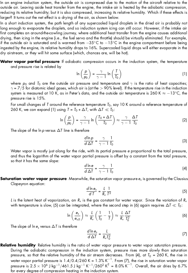
In response to Peter’s question about the effect of compression in the induction system, I did some calculations. On the net, compression leads to a drop in relative humidity, as expected.
Many thanks for the time you have put into that analysis!
I am not a physicist, @jmuelmen but the thing which was confusing me, and continues to do so, is: where will the water go when you warm up the air and then cool it down again, without having somewhere to drain off the (liquid) water?