Peter wrote:
I don’t understand the above.
It’s a very weak analog system, which is close to all kinds of high power signals, so it is easy to get interference which can cause offset, something might have changed during maintenance, while the battery was changed (not sure if the battery was changed during maintenance).
Newer Cessna’s have this “black box” under the cowling, where all electrical system relais, current sensor, voltage sensors are located. As part of maintenance some of these functions should be unconnected, tested and reattached, this is possible where you can influence the system as well.
Peter wrote:
It would be plausible in a scenario where the G1000 maintained config parameters in groups according to the subsystem, and upon encountering corrupted / out of range values in one group it reset that group to factory defaults.
It doesn’t do such “auto” repair actions.
It’s a very weak analog system, which is close to all kinds of high power signals, so it is easy to get interference which can cause offset,
Not if it is designed properly. It is a high-side shunt, which is a slight extra challenge (measuring say 75mV floating up at +28V is more circuitry than measuring 75mV at ground level) but in electronics terms it is trivial. And why should extra interference be present after changing a battery?
Peter wrote:
You could borrow mine but shipping would be very expensive. The ammeter is however accurate to 0.1A or better.
OTOH you can check for zero current just with a meter across the shunt in the C182, whose location should be easy to find.
In the end, I will buy a Ground Power Unit, maybe I’ll find a good used one. For this time, will do differently.
Peter, would you explain to me in simple words, what is a shunt and what it is aimed for ?
Peter wrote:
It would be really funny if you reinstalled the Gill and the system read 0.0A That would be truly weird.
I no longer have the Gill available, it’s been rubbished now !
@Jesse wrote:
Is the black box with battery relays, current sensor etc opened, to do the testing of the overvoltage etc (this would be regular maintenance) while the battery was changed?
Jesse, thank you for popping up, that’s nice to you !
You are right, during this annual, the over voltage protection test has been performed.
For memory, it consists in applying, if I recall correctly, more than 28v (I think it was using alcaline batteries, 4*9v) at the JBox, and check if a breaker (I don’t remind which one), strips out correctly. If it does, the protection works. I don’t remind exactly if it needed some wires to be disconnected and then reconnected. In that case, that could have created a new condition.
Thanks Jesse to have pointed out this.
Jesse wrote:
It’s a very weak analog system, which is close to all kinds of high power signals, so it is easy to get interference which can cause offset,
I understand this point, though I am not qualified to say if 0,5A is insignificant (on an analog device, in would be the width of the needle :-), or significant meaning.
As you see, the Concorde man is pointing directly towards a hot wired condition, while you seem to say it could have been enough ?
Jesse wrote:
not sure if the battery was changed during maintenance
It was changed actually.
From Gill G-243 to Concorde RG24-15M. For the record, my first Gill died when I was on a trip (the shop came to help with a Citation !). The second one didn’t pass the second annual. So I requested a Concorde this time.
would you explain to me in simple words, what is a shunt and what it is aimed for ?
It is a means of measuring large currents, without having to pass the said current all the way to the indicating device, via the thick wires which would be required.
This one generates 50mV for 500A so its resistance is 0.0001 ohm.

So to make an indicator which measures 500A you need a voltmeter which measures 50mV, and that’s easy to arrange.
Aircraft shunts are vaguely similar in general appearance.
Thanks Peter, I think I get it.
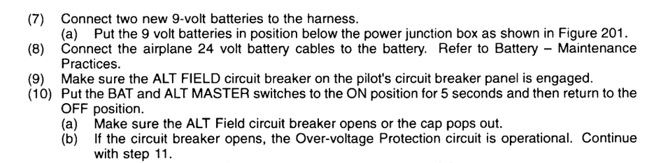
Dealing with the Alternator Control Unit test, here are the steps, and illustration to the J-Box (Master Control Unit box), with the 2*9V harness depicted.
You can see the different connectors / relay (starter, battery and alternator). As well as the ammeter (CS-3200).
The maintenance operation doesn’t seem to touch anything related to ammeter readings… Except if they touched something else “by accident”.
@Peter, do you recognize the shunt here ? Can you point it (them) out ?
PS: the JBox is fixed at the left side of the firewall (engine side of course).

Extension question: with engine OFF and battery powered (ON), the main battery will output current to feed the main bus, something like -4,5A, which I can read on the PFD.
Can one check this current flow at the junction box (if yes, where ?), and compare it to the PFD reading ?
If I measure 4A for example, then one will conclude the offset reading.

Touching a voltmeter at the two points indicated by arrows should show if there is any current flowing through there. You will need a decent voltmeter; a digital voltmeter with a 200mV smallest range ought to do.
However it may be that this is not a shunt. It may be a Hall Effect sensor and yes they do have all sorts of accuracy issues, both with the zero offset and full scale errors, hence calibration may be needed. I should have thought of this possibility. IMHO it would be an over-complicated way to do it but…
I can’t answer the rest; it depends on how it is wired.
I see the Garmin dealers are silent 
A Hall effect sensor is a transducer that varies its output voltage in response to a magnetic field. Hall effect sensors are used for proximity switching, positioning, speed detection, and current sensing applications.1 (Wikipedia)
Peter wrote:
Hall Effect sensor and yes they do have all sorts of accuracy issues, both with the zero offset and full scale errors, hence calibration may be needed.
This may correlate with Jesse suggestion, that the slightest modification may have induced a new offset. The point is, contrary to different stories I have read, my ammeter is not showing instable bullshit, i.e. rollercoaster between -15A and +15A. Hence the ammeter may be good per se.
Peter wrote:
IMHO it would be an over-complicated way to do it but…
What would be over complicated ?
This is a new CS-3200 Lamar ammeter. Rather cheap in aviation terms…

What would be over complicated ?
Using a Hall Effect sensor for something so simple.
But it’s not clear – look at this [ local copy ]
my ammeter is not showing instable bullshit
Hall effect sensors are not that bad. They are solid state devices which measure a magnetic field – in this case one produced by the current flowing through the shunt. It is an easier way (for a lazy designer) to measure current in a conductor which is at +28V rather than ground.
They just don’t have a precise zero – unlike a normal shunt which outputs absolutely no voltage when there is no current.