If it could be regarded as a Minor Alteration, it would be easy, but nobody I have spoken to thus far thinks that would get past any FAA inspector.
AC43-11 Appendix A lists Major mods and uses the words "basic change to" ... the fuel system or the electrical system.
I could argue that there is no basic change to the fuel system (just the elbow) and that's probably right. I am familiar with very similar mods to oil systems (fitting a backup oil pressure gauge for example, where you put a T-piece into the pipe and install a TSOd indicator) which were done on that basis and informal views from some DERs and DARs were 100% behind the Minor route on those.
But from what I hear all the backup alternator installs are done as Major mods so I guess that people have looked at it from the electrical point of view and concluded it is a basic change there. It is possible that all of them were misguided (in this business one can never be sure... in the land of the blind, the one eyed man is King) but it's not likely.
For the TB20, there is no airframe-applicable STC for this (or any other) alternator, so if one works on it being a Major mod it has to be done as a Field Approval.
Any Major mod is a 337. If there is an STC you still fill in a 337 but the papers are sent to the FAA for filing only.
In this case, myself being Europe based, I would have to find somebody in the USA willing to sit across a desk with an FAA FSDO inspector and negotiate this with him. I have done this twice already but have no contacts left out there. I heard today that the Frankfurt FSDO no longer does field approvals.
The T-piece fitting is made by Socata. I guess the pump end and the switch port are NPT (being American) and the hose end is probably ISO (metric). There are other fitting like that in the TB20. Socata sell them for c. €500 which reflects their silly manufacturing cost. Thankfully one never needs to replace them - unless some monkey strips the thread.
There is a problem fabricating such a T-piece from fresh, in paperwork terms. It is easier if it is assembled from some off the shelf aviation parts. It looks like a male-female NPT-NPT elbow would do it, and one would keep the existing T-piece with the pressure switch in it.
I've just had a closer look at this, during a 50hr service.
It clearly looks like a simple anticlockwise rotation of the existing elbow, to get the pressure switch out of the way, will do it
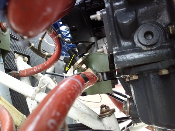
Obviously the elbow will need to be unscrewed completely, and screwed back in with a suitable sealant, otherwise it will just end up loose.
I am going for a 337 field approval, via a contact I found in the USA. The great thing about a field approval is that there is absolutely no way for the FAA to argue about it afterwards.
Another little update:
We are trying to find out whether that unused drive is for a magneto or for a vacuum pump.
The most probable thing is that it is for a magneto, and then you have to use a Lyco 71675 converter which looks like this
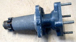
to convert it into a vacuum pump drive.
Apparently some people use this to drive a hydraulic pump, but I struggle to think of what that might be needed for. Pumping the retractable gear?
It clearly looks like a simple anticlockwise rotation of the existing elbow, to get the pressure switch out of the way, will do it. Obviously the elbow will need to be unscrewed completely, and screwed back in with a suitable sealant, otherwise it will just end up loose.
An additional male/female NPT extension would provide two threads over which to distribute the angle change. FWIW note that AC 43.13 does not allow teflon tape for fuel systems - which would otherwise be a common tactic to resolve this issue.
The electrical installation strikes me as the bulk of the approval, assuming the accessory drive is up to the job mechanically.
I've recently been looking over the potential for a quite similar retrofit installation of an additional (new design) high output PM alternator to a turboprop - but the airworthiness approval in this case would be non-FAA/DOT.
A couple of things this leads to:
I need to get hold of one of these adaptors, and if it fits and works then I need to check that the alternator doesn't hit anything - because it will end up about 30mm further out.
If it does hit something then swapping it with the vac pump would be the next step.
The suprising thing is that there appears to be no knowledge out there. One would think that a firm like B&C would be initimately familiar with the various internal engine layouts. I wonder if somebody has the email or phone # of a real tech contact inside Lyco? Normal emails to Lyco go nowhere.
Update:
Finally, after pulling teeth for some weeks, I got a useful and (if the C4D5D parts catalogue is correct for my engine) probably correct answer from Lyco.
Earlier on, they said "The hydraulic pump drive operates on a 1.300:1 drive ratio as well, but runs clockwise (as said in a previous email)." which is completely useless because there is nothing useful behind that blank cover.
That 3rd drive point (the other two being the vac pump and the single shaft dual mag) contains a blanking plug (a short shaft which has no gear teeth on it and just sits there) which cannot be removed without removing the accessory gearbox casing, which in turn probably needs the engine to be extracted from the aircraft (or at least pulled up on a crane, enough to get access).
I suspected that blanking plug is there because even though the IO540-C4 shows a proper accessory drive, the -C4D5D shows just a blank shaft stuck in there.
Lyco suggest using a DER. But if the FAA signs off on a Field Approval, that is also good enough. A DER 8110-3 would merely avoid the need to get any FAA approval; one would just file the 337 to Oklahoma.
I am not sure what I can do at this point, economically, other than get the paperwork sorted out and do it at the engine overhaul, which is a few years away... Perhaps one can get enough access by lifting the engine up a bit and tilting it forward.
The suprising thing is that nobody seems to have been up this road before, on an engine which is fairly common.
A different solution would be to ditch the vacuum pump and simply mount the B&C alternator in its place. That would be trivial but it lands you with a definitely nontrivial job of certifying the aircraft without a vacuum system. That is probably impossible if the B&C alternator drives a common bus with the main alternator (which is exactly what it does do).
I have seen a P210 with a 2nd battery that can be manually connected to the avionics bus via a switch. Very useful when operating the avionics on the ground (program flight plan, update map) and in case of an alternator failure.
I think this would be a much better solution than a 2nd alternator. And with a lithium battery the weight of a backup alternator, one gets a lot of extra time for not much money and effort. I'm looking into this modification.
A second battery, to be of any use, is going to be at least as big as the current one, so extremely heavy.
And I would not have a lithium battery (of that size) in the plane...
Scared of the Dreamliner-effect are you.
Why not? I guess you also wouldn't drive an electric car?
Good pedelecs are 24V. Their batteries have a good track record. Energy density is order of magnitude higher than lead acid batteries and you wouldn't use it to crank the engine. I will see if my shop agrees to such a setup without a lot of paperwork but I definitely want it. I am thinking of a long battery (like in some pedelecs) with a mount under the floorboard of the airplane.