
For avionics, the usual wires are these. They are available in several strengths, a common one being 20GA. What are the criteria for the strength? Is there anything in the aircraft legislation (FARs) or generally accepted industry standards? I'm looking for the right type of wire for a 15A/28V power connection and I have the feeling that my stock of 20GA wire won't do...
Also which connectors do you prefer? I've seen all kinds of connectors used in aircraft, even these and the round ones found in (old?) cars. I like the knife terminals better.
I will leave it to a specialist to dig out a table of current ratings versus AWG size, and circuit breaker ratings, but for joints within a harness... it depends on access, whether your fingers are about to freeze and fall off, and whether it is your plane or a customer's...
Personally I solder a joint and then heatshrink it. On a heavier cable, say 12 AWG, I would heatshrink twice because a normal heatshrink is fairly thin. Obviously this requires soldering competence, which is why many avionics installers avoid it, and also soldering can be difficult due to access.
One "proper" way which is widely used is a double ended crimp splice - a bit like these. These can be expensive; of the order of €1 each.
BTW do not use lead free (e.g. SAC305) solder on aircraft. It is extremely brittle. It just about works for PCB (SMT) soldering because the stuff doesn't move...
The www must be full of wire strength tables, and no two identical. One I have here states AWG14 as sufficient up to 18 ampere, whereas the next size AWG16 only takes 12 amps. Another tables says AWG14 can take 20 Amps, AWG16 taking 15.
Mind you there are several secondary factors: maximum ambient temperature, number of wires tied together, and most of all wire length.
Surprising how the weight goes up with diameter: AWG12 (good for 24 amps) weighs twice as much as AWG16.
BTW where does this AWG sizing system come from? Do the numbers actually stand for something? I much prefer cable section in mm2 !
As for terminals: I use the automotive style "Flachstecker", not least for easy connection to all accessories which are also from the automotive world; but had never seen these knife terminals - they do look interesting.
For avionics (or what counts as such in a microlight...) I prefer the 4mm Flachstecker.
What do you use to crimp those butt splices? They are really expensive, considering that the non aviation version costs next to nothing.
PS: I just noticed that Klauke, the German market leader for butt splices, belongs to the same company that owns Cessna. Maybe that means I can actually use those in the aircraft 
Regarding the "Flachstecker", they are PIGD FASTON receptables and common in automotive. I did use them before but got ridiculed by my avionics shop for using car stuff. They liked those knife connectors but not because they are expensive -- they were not mentioned on my invoice.
Browsing this section on Spruce is interesting -- butt splices, PIGD receptables, terminal nipples. I think I better turn off my adult content filter in the browser to see them all...
One uses a standard crimp tool e.g.
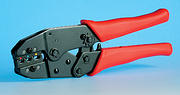
It has to be the right one for the terminal and you need to be really careful because the whole business of crimping hangs totally on exactly the right compression. The proper crimp tools have a ratchet preventing a premature release and are not cheap. Some (not this style) cost up to €1k, and I have one of those too - an ex UK Air Force 1960s one I picked up on Ebay for very little.
BTW here is another butt splice.
Re those blade connectors, I would never use one on my plane. I know they are widely used on planes (example) but they corrode, and these kinds of joints are an absolutely prime area for intermittent problems on the decades-old planes that dominate today's piston GA. Even on cars they are rarely used by the better quality makes, outside the passenger compartment.
Why do you want to use connectors? The wiring should be end to end, with no joints.
Why do you want to use connectors? The wiring should be end to end, with no joints.
Agree, I was thinking terminal connectors, but there are items like CHT sensors that only come with 6" tails, here I would prefer soldering, by splicing the wires together, then taking a single strand from an off cut and wrapping it around for a good inch, then soldering and as you say double heat shrink.
When building the RV I estimated that it would cost over £5000 just for a few wiring tools, I just got the standard crimp tool, just like the one you pictured and a Sub D crimp tool. The rest I got pre-made with wire attached.
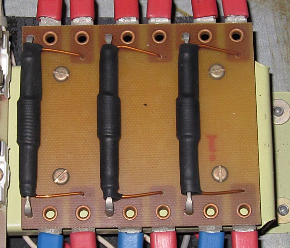
Yes; the CHT and EGT sensors from JPI come with these sorts of terminals, which are joined with screws and then covered up with a heat resistant fibreglass sleeve. It's really messy and bulky and probably accounts for many CHT and EGT indication problems.
Unfortunately thermocouple wire is difficult to join - other than with crimps. Also the probes do fail (the EGT ones, anyway, by hot gas erosion) so they need to be field-changeable and that is probably why JPI went for those connectors because they just need a spanner.
If it wasn't thermocouple wire, I would solder and heatshrink.
When building the RV I estimated that it would cost over £5000 just for a few wiring tools
I wonder what those were. Actually the crimp tool for the really good quality sub-D conns is the most expensive one of them all
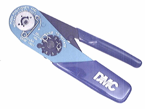
The pins are c. $2 each, as well! I think they are too expensive and I use machined pin conns and solder and heatshrink them. OK if you can prebuild the harness on a bench; much harder in the aircraft.
A good series I can recommend for wiring, bonding, tools, how to lace correctly etc..
to answer the question
With these you can look it up in the graphs and select the correct wire size
as an example 28 V/15--20A -->10 feet -->would put you somewhere btw AWG 16 and 14...
This is why they went to 28V to save some weight ..;-)
One further comment: crimping is far more easy performed then soldering as the hazard of soldering in the aircraft should be tackled very carefully.. Soldering is for component, bench repairs, crimping is for insitu aircraft installations


