
I had to scrap a flight today due to an ALT 1 overcharge warning on a Cirrus SR22G2, associated with an ammeter reading of +100 A (max deflection)
There were no indications of any such issues after my last flight, and the plane had not flown since.
Has anyone seen this before, or has otherwise a suggestion as to what it might be?
24V is correct for a charged battery without any current going in our out.
28V is correct for a battery being charged from a 28V bus (ahem, obviously  )
)
If the meter is reading 100A with engine not running then you must have a nuclear fusion power plant in there somewhere  But if the 100A was going into the battery, it would not be reading 24V. It would be boiling pretty soon. And if the 100A was going anywhere else then (24×100=2400W) there would be a lot of smoke coming out of something….
So I reckon the ammeter is duff.
Interesting the overcharge warning is present with the battery voltage showing 24V (which BTW is trivial to verify with a voltmeter on the battery). They are probably driving the indicator light from the current going into the battery, which would be an “interesting” approach… and if they are, the warning is probably being generated by the (probably duff) ammeter.
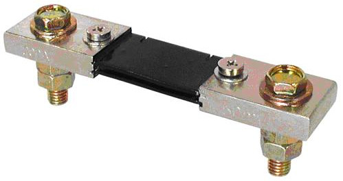
The ammeter is normally a voltmeter measuring a small voltage, say 100mV, dropped across a shunt which possibly looks something vaguely like this and if you put a voltmeter across it’s terminals, where the two thin wires come off to go to the ammeter instrument, you can check the voltage drop across it. It’s likely to be c. 100mV or of that order. But frankly, a 100A reading with the engine not running and the battery showing 24V, is totally not credible.
The shunt could be broken also. But if it was actually broken then no real current could flow through it and you would soon see some electrical problem.
That all makes sense.
According to the electrical system description in the AFM:
The amps indication is derived from current transducers located in the MCU. Output from each alternator and BAT 1 is measured. When the engine is operating and the ALT 1 and ALT 2 Master switches are ‘on’, the ammeter indicates the charging rate applied to the batteries. In the event the alternators are not functioning or the electrical load exceeds the output of the alternators, the ammeter indicates BAT 1 discharge rate. Alternator ammeter indications are positive only.
So I guess this is one of the dreaded MCU/FCU issues…
