You could knock that up with some AHRS module which has an analog output…
Now I want a KI256 version 
Thanks guys!
So tit seems he idea is not that stupid?
Anyone here who would be willing to help me actually build this? I do have a spare AHRS from LEVIL.
Heck we might even be able to certify it and save a few hundred of “old fashioned autopilot” victims?
Just to get me started: am I correct to assume that
- the rate of turn signal (calculated from the AHRS output) should be connected to pin #24
- its “ground” to connector pin #6 of the autopilot?
And I should reverse engineer the output on pin #5 to keep the STEC55X computer happy?
The key question is of course: how to convert AHRS output into a rate of turn analog signal…
The first step to reverse engineer something is US Avionics Ebay. You see a few there for a few hundred $; apparently working.

Then you need the MM, ideally, to get the specs. Then you need a clever electronics guy (or a girl)  It would take about a month, assuming the person is familiar with AHRS, knows (or knows somebody who knows) a bit of maths to do coordinate translation etc, and has ready expertise on a suitable CPU platform (e.g. some ARM or such, preferably with floating point maths) and A-D and D-A conversion.
The more pressing point is that anybody who sees your plane and the autopilot but doesn’t see the STEC TC and knows a “bit” about avionics" will ask “where is the TC?” So, to guard against anyone with an agenda, you probably should built this into an empty STEC TC housing
Just spoke to a guy who knows these. The output is from -1V to +1V for the turn rate. The “tacho” output is taken as “valid” by the autopilot at something like +8V. Best thing, like I said, would be to buy an old one and see what it does. The function appears to be completely trivial.
Peter you are confirming my gut feeling. As to keeping the TC on board well look at my instrument panel.
(insert pic here)
Can you see it? Rrrrright behind the iPad.
I would of course never ever consider the idea of having both the TC and the TC emulator on board with a hidden switch that is solely used for ground testing of the emulator…
Jokes aside – if it is a relatively linear depiction of turn rate (which really is degrees of heading change per second) then maybe a simple OpAmp would do the trick?
Who needs a CPU for this?
I have never designed anything with an AHRS, but if I was, I would buy one of the ready-made AHRS modules. These are temperature compensated and trimmed, so the really crappy drift of a cheap (anything below a fibre optic gyro) AHRS becomes, ahem, almost not very crappy at all
But I think these give you the pitch and roll signals, not a turn rate. One could mathematically derive a turn rate from the others, I think, but I have no idea how. You may need a roll angle together with a [rate of change of] heading… One guy who was really clever with this stuff was @DavidS and @Lionel may know too.
Obviously if you could get an AHRS module which outputs the rate of turn directly, in analog, you are done. You just need to fake the “tacho” signal.
“Obviously if you could get an AHRS module which outputs the rate of turn directly, in analog, you are done”.
http://watson-gyro.com/product/rate-gyros/solid-state-angular-rate-gyro-ars/
Or that?
http://www.strainsense.co.uk/products/angular-rate-gyros/12206ac-uniaxial-angular-rate-gyro
That looks interesting. I wonder if the specs are good enough, with sufficient stability, for the 3 degrees per second (full scale) which you are looking for?
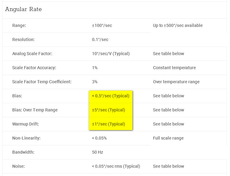
Also it doesn’t look like it is temperature stabilised so you would need to implement that

Peter I think 3 degrees per second full scale is not enough. More like 30? We’ll need testing.
I have asked them for a quote and also found another type which IS temperature stabilized. It uses a panasonic chip
(It seems that these sensors are very common in the automotive industry so they should be cheap)
Output voltage has a midpoint at +2.5 V and very low current which is a small nuisance (need to implement the offset to achieve a +/- 1 V full scale swing and increase current capability probably.)
Version R050 does 50 degree per second full swing and gives 25 mV per degree/sec, so that would be 1 V for 40 degree per sec. Seems like a good starting point..
Summary of project:
- make/find a test bed (rotating table, 24 V power supply, 2 voltmeters)
- Buy a used TC
- Buy a solid state sensor which will also be used as the rate of turn measurement instrument on the test bed
- Install, test and map the characteristic of the mechanical TC
- Select the most appropriate off the shelf sensor type
- More testing
- Implement the additional electronics to emulate the +/- 1 volt. This will need some careful design as it will become the weak link…
I wonder how much better the AP will work with this…
I know Sparkfun has a 6dof IMU module:
https://www.sparkfun.com/products/10121
More than you need for a TC but they have a whole range of breakout boards for things like this.