A little update:
The TKS system has been tested in some real icing conditions.
It works great. I had best part of 30mins in pretty bad icing, with occassional accretion rates of ~2cm in 5 minutes
and it coped with it fine albeit only at max flow rate. At the lower flow rate it might cope with a few mm in 5 minutes.
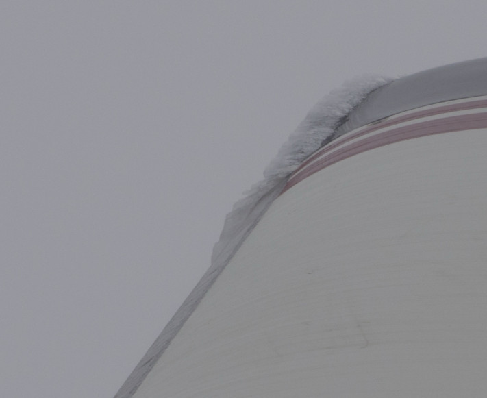
It does leave lots of lumps which slow you down, like the one above, and this sort of thing where the panels join up
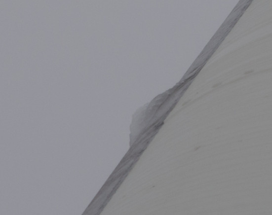
and these do have an impact on speed – perhaps 10kt in total. This is of course compared to the plane being totally unflyable (in level flight) if there was no TKS and it was covered all over like that (I know about that too; Vs goes up to some 110kt, etc; posted that previously).
The stall warner gets frozen over pretty early on. Hence my post here but it looks like nobody here has an AoA sensor and has used it at any altitude.
Filling the system using the method in the video above is satisfactory, but the way the filler door fits isn’t because flying in rain will deposit a lot of water into the rear hull. The door needs to be modified and I have some ideas. Replacing the door with a much stiffer (stainless steel) version would enable a rubber seal to be fitted. Currently I tape over the door gap with some 5mm wide clear tape.
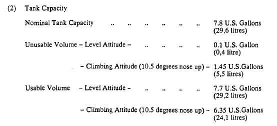
The TKS liquid level readout is accurate but is hugely sensitive to the pitch angle. You can have it showing 7 USG at 2.5deg up (the usual cruise attitude for most planes) or 5 USG at 7 deg up.
I forgot, what’s the total quantity of TKS fluid in TB20?
BTW in DA42 there are three flow rates of fluid: normal, high and max. Normal is periodical on and off, high is constant rate and max is constant rate with both pumps engaged and it’s limited to continuous 5 minutes.
I’ve just been to the plane to top off the TKS and found some fluid having sprayed evidently out of the filler cap into the rear hull cavity. This is really bad because it is corrosive. It doesn’t appear to have sprayed towards the front where it would have covered the Sandel SG102 AHRS box (installed in the old KG102 gyro location) but it sprayed towards the rear. I need to wipe it up and brush a load of ACF50 in there. Most owners would have never spotted this because they never look under inspection covers and I dare say most companies would not have spotted it either…
I reckon it happened because I over-filled the system before the long trip to Greece and even though I ground ran it to bring the fluid level back down, to roughly the top of the tank, that wasn’t low enough, and some sloshing around pushed the stuff out of the filler. The filler cap has a one-way mechanism to let air in but keep the fluid from escaping and this obviously isn’t working.
As I wrote before, the whole filler door assembly is poorly designed. It is “traditional aircraft stuff” i.e. how it has always been done in GA, but it would have been much better to have a proper filling point inside the luggage compartment. It would have just been illegal re the 35 year old STC to not install that filler door… but doing stuff the right way is often illegal. I might install the proper fill point one day.
I think there is a design defect which makes the above TKS spray inevitable. The tank has no baffles so as the liquid surges towards the back, where the fill point is, it will shoot up the filler pipe and shoot out of the vent hole there. It does so with quite a bit of force. This is serious and will need a vent tube to be installed. Most owners would never notice because they never look into the internals of their plane, and I suspect most mechanics would not notice the stuff in there either.
On another topic, I have just seen a TB21GT with TKS, a well known one, and the elevator panels were not fitted according to the STC. Instead of the offset shown here the panels are in line with the elevator. Obviously the installer didn’t read the drawing and if it was who I think it was that is as expected!
Mine doesn’t have the offset on the elevator, at least as I remember. I will have a closer look tomorrow, however I don’t see why would that be important…
Maybe an extra 2% upward force on the elevator causing an imperceptible nose down attitude easily correctable with some trim.
I think it makes much more difference than 2%.
However the reason for it remains a mystery.
Alex, what IAS do you see at say 2000ft, 23" 2400rpm 11.7 USG/hr?
Peter wrote:
However the reason for it remains a mystery.
It’s got to do with the position of the LE stagnation point in whatever critical certification scenario they considered (was it ever JAA-certified for icing conditions?). The panels are supposed to cover a certain amount of LE downstream of the stagnation point in that condition.
BTW, great pics and very effective (at least at high flow).
That is a superb article you found, Antonio [ local copy ].
I am not aware of any FAA-FIKI certification attempt but maybe @TKS would know – his firm did the original development of this system. You would have to do an STC which includes a second alternator and a heated stall warner.