Ultranomad wrote:
I get an impression that a major reason behing notoriously high costs of certification is the lack of design effort to make it cheaper by using technologies that make the fulfilment of some certification requirements either automatic or at least easier.
I imagine so because that requires understanding the requirements before you start. Not designing it first and then muddling through certification, patching issues as they appear.
LeSving wrote:
A certified Trig radio doesn’t cost much more than a non certified MGL.
Even that MGL has to be certified as a radio, otherwise it would be illegal to transmit using it. That should be the hard part.
LeSving wrote:
Glass panels are a whole different thing though, but a non certified g900x system costs at least 70k, almost 10x as much as a roughly equivalent Dynon system or g3x touch system from Garmin.
That’ll be because G900X is based on G950/ G1000 which isn’t cheap. And there’re people who spend that much on avionics for a homebuilt.
Sure certification is easier once you know how and design it to meet the spec. This is true for any standard. It gives an advantage to big old companies with, ahem, good lunching contacts inside the certification bodies, and makes it potentially impossible for newcomers to the market. I once tried to launch a BASEEFA approved product and the guy on the phone practically told me to get lost!
I guess that Avidyne didn’t do that very well with some recent products which is why it took such a long time.
Martin wrote:
Even that MGL has to be certified as a radio, otherwise it would be illegal to transmit using it
I checked all this half a year ago. The MGL has been tested and found OK some years ago on 25kHz separation. Today the telecom authority do not do this kind of testing/investigation anymore, they rely on adherence to specs by the manufacturer. The easiest way for the manufacturer to show it is OK as a radio in an aircraft is therefore to certify it. They could also test it according to the standard for ground based equipment, but MGL was not interested in doing that. A new radio has to be 8.33 today, and therefore the MGL is illegal. According to MGL the radio is built from the ground according to the specs, but as long as it is not certified (or tested) this means little. It is not the aviation authority that approves radios. In a non certified aircraft you can use an approved ground based unit or a certified aircraft unit, but not a non certified aircraft unit.
I think Garmin only elevates the prices for the g900x because of the insane prices of the g1000. The g900x is built using un-certified components, just like the g3x, but it uses the “architecture” of the g1000. If you got that kind of money, it is a bit strange that people would buy the g900x instead of the certified g1000.
If you got that kind of money, it is a bit strange that people would buy the g900x instead of the certified g1000.
I don’t think you can buy a G1000.
Certified Garmin stuff is sold only via authorised dealers and one of these is not allowed to sell you a G1000. Well, not for use in an aircraft. The G1000 is not certified except for OEM installs and some retrofits e.g. TBM700.
Well, I am 100% sure I could find a contact who would sell me a complete G1000 system, but it would be off the books and no warranty. I can similarly buy a G500 or an IFD540 but there would be no warranty on them; I would have to return the stuff to my contact. If I tried to return it to the mfg they would quite likely declare it a grey import and not touch it.
There is a separate channel, established in the USA but not discussed openly in much detail for obvious reasons, where an Experimental owner can buy some certified avionics “off the process” and still get a warranty. Avidyne and Garmin offer this (they have said so on forums there). I don’t know how much proof they need of the aircraft details… I bought a Sandel EHSI in that way, with a (nonexistent) “Experimental harness”. This happens quite a bit.
LeSving wrote:
It is not the aviation authority that approves radios.
I know. That’s why I wrote “as a radio,” not as avionics. I don’t know why you’re making such a mess of it. Certification is not something limited to aviation and there are many standards to certify a product against. Just so you can sell it, it’ll have to go through certification to establish it’s safe to use, it doesn’t cause interference. And because it transmits in a licensed spectrum, it stands to reason it’ll have to meet certain standard (just like the radio module in your phone). And if you want to install it in a “non-Annex 2” aircraft, it will need some more certification – I imagine this wouldn’t be the problematic part because connectivity is normally very limited.
LeSving wrote:
If you got that kind of money, it is a bit strange that people would buy the g900x instead of the certified g1000.
That’s simple, Garmin won’t sell it to you. And it would be even more expensive (really, 70k is more G500 based cockpit territory). IIRC even G900X is available only for certain kits. Perhaps that changed, I don’t watch non-certified avionics much.
it doesn’t connect to anything
A radio with a NAV section can drive a CDI, an HSI, an autopilot, etc.
Peter wrote:
A radio with a NAV section can drive a CDI, an HSI, an autopilot, etc.
I was talking about a pure radio like the little Trigs. However, “anything” was an exaggeration (should have read it through properly before submitting) so I amended that statement.
Martin wrote:
so I amended that statement
Which is an AMC for EuroGA forum post certification, so yep, approved ;-)
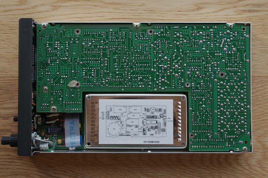
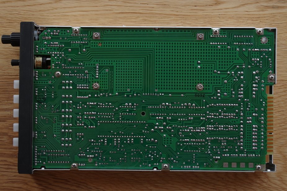
Here is the KR87 ADF. I did not dismantle further because it is a spare unit on the shelf.
Martin wrote:
I don’t know why you’re making such a mess of it.
I’m not making the mess, it IS a mess. It has become a mess in later years since the authority stopped approving stuff by testing etc. There is no requirement for a radio to be certified, but that is now the only way for the authorities to “approve” a radio. That’s the telecom authority, the aviation authority couldn’t care less.